


CHAPTER 6 CIRCUIT DIAGRAMS
TABLE OF CONTENTS
Inter Connection.......................................................................................................................6-3
Circuit Diagram (Main PCB 1/14) [CPU 1/2] ............................................................................6-4
Circuit Diagram (Main PCB 2/14) [CPU 2/2] ............................................................................6-5
Circuit Diagram (Main PCB 3/14) [ROM] .................................................................................6-6
Circuit Diagram (Main PCB 4/14) [RAM] ..................................................................................6-7
Circuit Diagram (Main PCB 5/14) [Custom IC] .........................................................................6-8
Circuit Diagram (Main PCB 6/14) [Head Control].....................................................................6-9
Circuit Diagram (Main PCB 7/14) [PF Motor Control] ..............................................................6-10
Circuit Diagram (Main PCB 8/14) [Sensor] ..............................................................................6-11
Circuit Diagram (Main PCB 9/14) [Power/Buzzer] ...................................................................6-12
Circuit Diagram (Main PCB 10/14) [Connector] .......................................................................6-13
Circuit Diagram (Main PCB 11/14) [Cutter/Peeler] ...................................................................6-14
Circuit Diagram (Main PCB 12/14) [Centronics I/F]..................................................................6-15
Circuit Diagram (Main PCB 13/14) [Serial I/F]..........................................................................6-16
Circuit Diagram (Main PCB 14/14) [USB I/F] ...........................................................................6-17
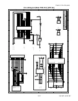
Circuit Diagram (Power Supply PCB (120V))...........................................................................6-18
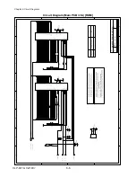
Circuit Diagram (Power Supply PCB (220V))...........................................................................6-19
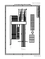
Circuit Diagram (Ribbon Main PCB 1/4) [Motor Control]..........................................................6-20
Circuit Diagram (Ribbon Main PCB 2/4) [Motor VCC Control] .................................................6-21
Circuit Diagram (Ribbon Main PCB 3/4) [Sensor] ....................................................................6-22
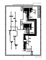
Circuit Diagram (Ribbon Main PCB 4/4) [12V, Fan & DIR SW Control] ...................................6-23
Circuit Diagram (Ope-pane PCB).............................................................................................6-23
Circuit Diagram (Ope-pane PCB).............................................................................................6-24
Circuit Diagram (Centro PCB)..................................................................................................6-25
Circuit Diag am (Tension Sensor PCB) ....................................................................................6-26
Circuit Diagram (Reflective Sensor PCB) ................................................................................6-27
Circuit Diagram (Transparent Sensor PCB) .............................................................................6-28
Circuit Diagram (Head Up Sensor PCB) ..................................................................................6-29
CLP-621 & CLP-631
6-2
Содержание CLP-621
Страница 1: ...Technical Manual CLP 621 CLP 631 Thermal Transfer Barcode Label Printer JM74961 00F 1 00E 0701...
Страница 2: ...CLP 621 CLP 631 ii Copyright 2007 by CITIZEN SYSTEMS JAPAN CO LTD...
Страница 4: ...CHAPTER 1 SPECIFICATIONS CLP 621 CLP 631...
Страница 13: ...CHAPTER 2 OPERATING PRINCIPLES CLP 621 CLP 631...
Страница 68: ...2 5 Power Supply CLP 621 CLP 631 2 56 N1 N2 N3 N4 BLOCK A BLOCK E BLOCK B BLOCK C BLOCK D 120V type...
Страница 69: ...2 5 Power Supply 2 57 CLP 621 CLP 631 N1 N2 N3 N4 Block A Block B Block C Block E Block D 220 240V type...
Страница 73: ...CHAPTER 3 DISASSEMBLY AND MAINTENANCE CLP 621 CLP 631...
Страница 126: ...CLP 621 CLP 631 CHAPTER 4 TROUBLESHOOTING...
Страница 138: ...CLP 621 CLP 631 CHAPTER 5 PARTS LISTS...
Страница 143: ...Chapter 5 Parts Lists CLP 621 CLP 631 5 6 DRAWING NO 1 General Assembly Rev 0 1 7 8 2 3 4 2 10 11 12 9 5 2 13 14 10...
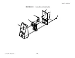
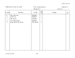
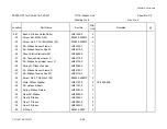
Страница 163: ...Chapter 5 Parts Lists CLP 621 CLP 631 5 26 DRAWING NO 6 Sensor U Unit Rev 0 4 16 3 2 1 9 10 11 5 8 6 12 7 13 14 15...
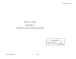
Страница 166: ...Chapter 5 Parts Lists CLP 621 CLP 631 5 29 DRAWING NO 7 Control Panel Unit Rev 0 4 3 2 1 5...
Страница 174: ...Chapter 5 Parts Lists CLP 621 CLP 631 5 37 DRAWING NO 9 Ribbon Unit Fan SA2 Rev 0 1 2 4 3 5 6 3...
Страница 177: ...Chapter 5 Parts Lists CLP 621 CLP 631 5 40 DRAWING NO 10 Accessories Rev 0 3 2 4 1...
Страница 179: ...CHAPTER 6 CIRCUIT DIAGRAMS CLP 621 CLP 631...
Страница 208: ...APPENDICES CLP 621 CLP 631...
Страница 211: ...B Mounting Diagrams B Mounting Diagrams B Mounting Diagrams CLP 621 CLP 631 AP 4 AP 4 B 1 Main PCB Main PCB Parts side...
Страница 212: ...B Mounting Diagrams AP 5 CLP 621 CLP 631 Main PCB Solder side...
Страница 213: ...B Mounting Diagrams CLP 621 CLP 631 AP 6 AP 6 B 2 Power Supply PCB 120V 220V B 2 Power Supply PCB 120V 220V...
Страница 214: ...B Mounting Diagrams AP 7 CLP 621 CLP 631 B 3 Ribbon Main PCB Parts side Solder side...
Страница 217: ......


