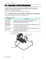


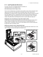


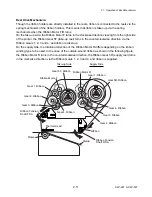


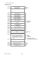


2-2. Operation of Control Parts
2-17
CLP-621 & CLP-631
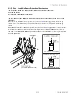
(4) Thermal print head
The thermal print head has the following thermal elements. It also has the print head driver
circuit.
• 864 dots for CLP-621
• 1275 dots for CLP-631
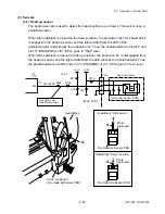
(5) Sensors
The following 7 sensors are used:
Sensor name
Description
Head Up Sensor
Photointerrupter.
Transparent Sensor
Photo sensor using the phototransistor.
Reflective Sensor
Photo sensor consisting of 2 LEDs and 1
phototransistor.
Tension Sensor (Front/Rear)
Photo sensor using the phototransistor. Located on the
front and rear of the Ribbon Unit.
Head Temperature Sensor
Thermistor incorporated in the print head.
PF Motor Temperature Sensor
Thermistor attached to the PF Motor.
Ribbon Motor Temperature Sensor Thermistor attached to the Ribbon Motor F.
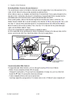
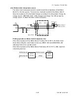
(6) Motor
Three motors are used. The PF Motor is a stepping motor to feed media. The Ribbon Motor F
and Ribbon Motor R are stepping motors to take up and supply ribbon, respectively.
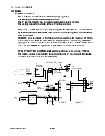
(7) Parallel I/F (IEEE1284)
This is the parallel I/F to transmit and receive parallel data between the printer and the host. It
supports Centronics Compatible mode, NIBBLE mode and ECP mode.
Parallel I/F, serial I/F, or USB I/F is automatically selected when data is received.
(8) Serial I/F (RS-232C)
This is a circuit to transmit and receive serial data between the printer and the host.
Parallel I/F, serial I/F, or USB I/F is automatically selected when data is received.
(9) USB (Universal Serial Bus) I/F
This is a circuit to transmit and receive serial data between the printer and the host using the
USB.
Parallel I/F, serial I/F, or USB I/F is automatically selected when data is received.
(10) Ethernet I/F (Option)
This is a circuit which supports Ethernet protocol. LAN connection is possible.
(11) Wireless LAN I/F (Option)
This is a circuit which supports Ethernet protocol. Wireless LAN connection is possible.
Содержание CLP-621
Страница 1: ...Technical Manual CLP 621 CLP 631 Thermal Transfer Barcode Label Printer JM74961 00F 1 00E 0701...
Страница 2: ...CLP 621 CLP 631 ii Copyright 2007 by CITIZEN SYSTEMS JAPAN CO LTD...
Страница 4: ...CHAPTER 1 SPECIFICATIONS CLP 621 CLP 631...
Страница 13: ...CHAPTER 2 OPERATING PRINCIPLES CLP 621 CLP 631...
Страница 68: ...2 5 Power Supply CLP 621 CLP 631 2 56 N1 N2 N3 N4 BLOCK A BLOCK E BLOCK B BLOCK C BLOCK D 120V type...
Страница 69: ...2 5 Power Supply 2 57 CLP 621 CLP 631 N1 N2 N3 N4 Block A Block B Block C Block E Block D 220 240V type...
Страница 73: ...CHAPTER 3 DISASSEMBLY AND MAINTENANCE CLP 621 CLP 631...
Страница 126: ...CLP 621 CLP 631 CHAPTER 4 TROUBLESHOOTING...
Страница 138: ...CLP 621 CLP 631 CHAPTER 5 PARTS LISTS...
Страница 143: ...Chapter 5 Parts Lists CLP 621 CLP 631 5 6 DRAWING NO 1 General Assembly Rev 0 1 7 8 2 3 4 2 10 11 12 9 5 2 13 14 10...
Страница 163: ...Chapter 5 Parts Lists CLP 621 CLP 631 5 26 DRAWING NO 6 Sensor U Unit Rev 0 4 16 3 2 1 9 10 11 5 8 6 12 7 13 14 15...
Страница 166: ...Chapter 5 Parts Lists CLP 621 CLP 631 5 29 DRAWING NO 7 Control Panel Unit Rev 0 4 3 2 1 5...
Страница 174: ...Chapter 5 Parts Lists CLP 621 CLP 631 5 37 DRAWING NO 9 Ribbon Unit Fan SA2 Rev 0 1 2 4 3 5 6 3...
Страница 177: ...Chapter 5 Parts Lists CLP 621 CLP 631 5 40 DRAWING NO 10 Accessories Rev 0 3 2 4 1...
Страница 179: ...CHAPTER 6 CIRCUIT DIAGRAMS CLP 621 CLP 631...
Страница 208: ...APPENDICES CLP 621 CLP 631...
Страница 211: ...B Mounting Diagrams B Mounting Diagrams B Mounting Diagrams CLP 621 CLP 631 AP 4 AP 4 B 1 Main PCB Main PCB Parts side...
Страница 212: ...B Mounting Diagrams AP 5 CLP 621 CLP 631 Main PCB Solder side...
Страница 213: ...B Mounting Diagrams CLP 621 CLP 631 AP 6 AP 6 B 2 Power Supply PCB 120V 220V B 2 Power Supply PCB 120V 220V...
Страница 214: ...B Mounting Diagrams AP 7 CLP 621 CLP 631 B 3 Ribbon Main PCB Parts side Solder side...
Страница 217: ......


