


2-2. Operation of Control Parts
2-31
CLP-621 & CLP-631
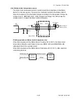
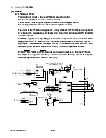
Thermal resistance check:
When the printer is turned ON, the thermal resistance check is conducted. If any fault is
found, it is memorized and, when the printer is turned ON next time, the CONDITION LED
and ERROR LED alternately blink on the operation panel.
During the thermal resistance check, pin 117 (HCVON) of IC11 (Custom IC) goes to "High"
level, and DTR2 and TR2 turn ON. Thus, +5V is supplied to the thermal head, instead of
+24V.
The following is a simplified circuitry under checking, where TR2 turns ON and a thermal
element "R" is selected. At the point "A", the voltage divided by R77 and R is developed.
The CPU monitors this voltage at pin 10 (HEADRES), and check if the voltage is out of the
allowable range or not. (For example, if R is open, the voltage at point “A” will be about
+3.3V.)
Each thermal element is successively checked in this way.
+5V
IC1
CPU
R77
R
A
R: Resistance of a thermal element
TR2
Thermal head
R83
HEADRES
ANI5
10
+3.3V
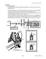
(4-4) Buzzer driver
This circuit drives the buzzer.
To sound the buzzer, the CPU outputs a pulse from pin 171 (BUZZER). The transistor
DTR4 turns ON and OFF, and the buzzer is driven.
IC1
CPU
BUZZER
+24V
[Main PCB]
P77
171
D11
R121
R118
DTR4
DTC143EUA
P225
R120
P226
BZ1
Содержание CLP-621
Страница 1: ...Technical Manual CLP 621 CLP 631 Thermal Transfer Barcode Label Printer JM74961 00F 1 00E 0701...
Страница 2: ...CLP 621 CLP 631 ii Copyright 2007 by CITIZEN SYSTEMS JAPAN CO LTD...
Страница 4: ...CHAPTER 1 SPECIFICATIONS CLP 621 CLP 631...
Страница 13: ...CHAPTER 2 OPERATING PRINCIPLES CLP 621 CLP 631...
Страница 68: ...2 5 Power Supply CLP 621 CLP 631 2 56 N1 N2 N3 N4 BLOCK A BLOCK E BLOCK B BLOCK C BLOCK D 120V type...
Страница 69: ...2 5 Power Supply 2 57 CLP 621 CLP 631 N1 N2 N3 N4 Block A Block B Block C Block E Block D 220 240V type...
Страница 73: ...CHAPTER 3 DISASSEMBLY AND MAINTENANCE CLP 621 CLP 631...
Страница 126: ...CLP 621 CLP 631 CHAPTER 4 TROUBLESHOOTING...
Страница 138: ...CLP 621 CLP 631 CHAPTER 5 PARTS LISTS...
Страница 143: ...Chapter 5 Parts Lists CLP 621 CLP 631 5 6 DRAWING NO 1 General Assembly Rev 0 1 7 8 2 3 4 2 10 11 12 9 5 2 13 14 10...
Страница 163: ...Chapter 5 Parts Lists CLP 621 CLP 631 5 26 DRAWING NO 6 Sensor U Unit Rev 0 4 16 3 2 1 9 10 11 5 8 6 12 7 13 14 15...
Страница 166: ...Chapter 5 Parts Lists CLP 621 CLP 631 5 29 DRAWING NO 7 Control Panel Unit Rev 0 4 3 2 1 5...
Страница 174: ...Chapter 5 Parts Lists CLP 621 CLP 631 5 37 DRAWING NO 9 Ribbon Unit Fan SA2 Rev 0 1 2 4 3 5 6 3...
Страница 177: ...Chapter 5 Parts Lists CLP 621 CLP 631 5 40 DRAWING NO 10 Accessories Rev 0 3 2 4 1...
Страница 179: ...CHAPTER 6 CIRCUIT DIAGRAMS CLP 621 CLP 631...
Страница 208: ...APPENDICES CLP 621 CLP 631...
Страница 211: ...B Mounting Diagrams B Mounting Diagrams B Mounting Diagrams CLP 621 CLP 631 AP 4 AP 4 B 1 Main PCB Main PCB Parts side...
Страница 212: ...B Mounting Diagrams AP 5 CLP 621 CLP 631 Main PCB Solder side...
Страница 213: ...B Mounting Diagrams CLP 621 CLP 631 AP 6 AP 6 B 2 Power Supply PCB 120V 220V B 2 Power Supply PCB 120V 220V...
Страница 214: ...B Mounting Diagrams AP 7 CLP 621 CLP 631 B 3 Ribbon Main PCB Parts side Solder side...
Страница 217: ......


