


7-7
Firepower 7000 and 8000 Series Installation Guide
Chapter 7 Hardware Specifications
Firepower 7000 Series Devices
See the following sections for more information:
•
Firepower 7110 and 7120 Chassis Front View, page 7-7
•
Firepower 7110 and 7120 Chassis Rear View, page 7-11
•
Firepower 7110 and 7120 Physical and Environmental Parameters, page 7-12
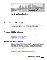
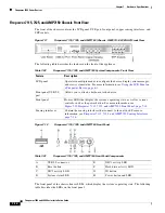
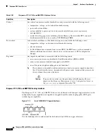
Firepower 7110 and 7120 Chassis Front View
The front of the chassis contains the LCD panel, USB port, front panel, and either copper or fiber sensing
interfaces.
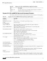
Figure 7-5
Firepower 7110 and 7120 with Copper Interfaces (Chassis: GERY-1U-8-C-AC)
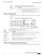
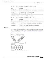
Figure 7-6
Firepower 7110 and 7120 with Fiber Interfaces (Chassis: GERY-1U-8-FM-AC)
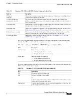
The following table describes the features on the front of the appliance.
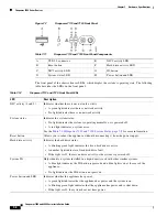
Table 7-10
Firepower 7110 and 7120 System Components: Front View
Feature
Description
LCD panel
Operates in multiple modes to configure the device, display error messages,
and view system status. For more information, see
.
Front panel USB 2.0
port
Allows you to attach a keyboard to the device.
Front panel
Houses LEDs that display the system’s operating state, as well as various
controls, such as the power button. For more information, see
Figure 7-7Firepower 7110 and 7120 Front Panel, page 7-8
.
Sensing interfaces
Contain the sensing interfaces that connect to the network. For more
information, see
Firepower 7110 and 7120 Sensing Interfaces, page 7-9
.


