background image


8-2

Firepower 7000 and 8000 Series Installation Guide


Chapter 8      Restoring a Firepower System Appliance to Factory Defaults

  Understanding the Restore Process

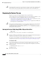
Restoring a Firepower device that is deployed inline resets the device to a non-bypass (fail closed) 
configuration, disrupting traffic on your network. Traffic is blocked until you configure bypass-enabled 
inline sets on the device. For more information about editing your device configuration to configure 
bypass, see the Managing Devices chapter of the 

Firepower Management Center Configuration Guide

.

Understanding the Restore Process

Access:

Admin

To restore a Firepower device, you boot from the appliance’s internal flash drive and use an interactive 
menu to download and install the ISO image on the appliance. For your convenience, you can install 
system software and intrusion rule updates as part of the restore process. 

Only reimage your appliances during a maintenance window. Reimaging resets appliances in bypass 
mode to a non-bypass configuration and disrupts traffic on your network until you reconfigure bypass 
mode. For more information, see 

Traffic Flow During the Restore Process, page 8-1

.

Note that you 

cannot

 restore an appliance using its web interface. To restore an appliance, you must 

connect to it in one of the following ways: 

Keyboard and Monitor/KVM

You can connect a USB keyboard and VGA monitor to the appliance, which is useful for 
rack-mounted appliances connected to a KVM (keyboard, video, and mouse) switch. If you have a 
KVM that is remote-accessible, you can restore appliances without having physical access.

Serial Connection/Laptop

You can use a rollover serial cable (also known as a NULL modem cable or a Cisco console cable) 
to connect a computer to the appliance. See the hardware specifications for your appliance to locate 
the serial port. To interact with the appliance, use terminal emulation software such as 
HyperTerminal or XModem. For more information, including a table of serial port connectors by 
appliance, see 

Serial Connection/Laptop, page 4-20

.

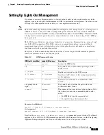
Lights-Out Management Using Serial over LAN

You can perform a limited set of actions on Management Centers and Firepower devices using 
Lights-Out Management (LOM) with a Serial over LAN (SOL) connection. If you do not have 
physical access to an appliance, you can use LOM to perform the restore process. After you connect 
to an appliance using LOM, you issue commands to the restore utility as if you were using a physical 
serial connection. Note that you can use Lights-Out Management on the default (

eth0

) management 

interface only. For more information, see 

Setting Up Lights-Out Management, page 8-15

.

Before You Begin

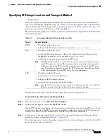
Obtain the restore ISO image for the appliance from the Support Site. See 

To obtain the restore ISO 

and other update files:, page 8-3

To restore a Firepower device:

Step 1

Copy the image to an appropriate storage medium.

Step 2

Connect to the appliance.

Step 3

Reboot the appliance and invoke the restore utility.

Содержание TelePresence Server 7010

Страница 1: ...co com Cisco has more than 200 offices worldwide Addresses phone numbers and fax numbers are listed on the Cisco website at www cisco com go offices Firepower 7000 and 8000 Series Installation Guide Version 6 0 November 5 2015 ...

Страница 2: ... OR IMPLIED INCLUDING WITHOUT LIMITATION THOSE OF MERCHANTABILITY FITNESS FOR A PARTICULAR PURPOSE AND NONINFRINGEMENT OR ARISING FROM A COURSE OF DEALING USAGE OR TRADE PRACTICE IN NO EVENT SHALL CISCO OR ITS SUPPLIERS BE LIABLE FOR ANY INDIRECT SPECIAL CONSEQUENTIAL OR INCIDENTAL DAMAGES INCLUDING WITHOUT LIMITATION LOST PROFITS OR LOSS OR DAMAGE TO DATA ARISING OUT OF THE USE OR INABILITY TO US...

Страница 3: ...ystem 1 11 Security Internet Access and Communication Ports 1 13 Internet Access Requirements 1 13 Communication Ports Requirements 1 14 Preconfiguring Appliances 1 16 Deploying on a Management Network 2 1 Management Deployment Considerations 2 1 Understanding Management Interfaces 2 2 Single Management Interface 2 2 Multiple Management Interfaces 2 2 Deployment Options 2 3 Deploying with Traffic ...

Страница 4: ...ents 3 18 Integrating with VPNs 3 18 Detecting Intrusions on Other Points of Entry 3 19 Deploying in Multi Site Environments 3 20 Integrating Multiple Management Interfaces within a Complex Network 3 22 Integrating Managed Devices within Complex Networks 3 23 Installing a Firepower Managed Device 4 1 Included Items 4 1 Security Considerations 4 1 Identifying the Management Interfaces 4 2 Firepower...

Страница 5: ...e 6 4 Network Configuration Mode 6 4 Allowing Network Reconfiguration Using the LCD Panel 6 6 System Status Mode 6 7 Information Mode 6 8 Error Alert Mode 6 9 Hardware Specifications 7 1 Rack and Cabinet Mounting Options 7 1 Firepower 7000 Series Devices 7 1 Firepower 7010 7020 7030 and 7050 7 1 Firepower 7110 and 7120 7 6 Firepower 7115 7125 and AMP7150 7 13 Firepower 8000 Series Devices 7 21 Fir...

Страница 6: ...8 11 Saving and Loading Restore Configurations 8 13 Next Steps 8 14 Setting Up Lights Out Management 8 14 Enabling LOM and LOM Users 8 16 Installing an IPMI Utility 8 17 Power Requirements for Firepower Devices A 1 Warnings and Cautions A 1 Static Control A 1 Firepower 70xx Family Appliances A 1 Installation A 2 Grounding Earthing Requirements A 2 Firepower 71xx Family Appliances A 3 Installation ...

Страница 7: ...ying the Module Parts C 3 Before You Begin C 4 Removing a Module or Slot Cover C 5 Inserting a Module or Slot Cover C 6 Scrubbing the Hard Drive D 1 Scrubbing the Contents of the Hard Drive D 1 Preconfiguring Firepower Managed Devices E 1 Before You Begin E 1 Required Preconfiguration Information E 1 Optional Preconfiguration Information E 2 Preconfiguring Time Management E 2 Installing the System...

Страница 8: ...Contents 6 Firepower 7000 and 8000 Series Installation Guide ...

Страница 9: ...at might affect the availability integrity or confidentiality of hosts on the network Inline interfaces receive all traffic unconditionally and traffic received on these interfaces is retransmitted unless explicitly dropped by some configuration in your deployment Inline devices can be deployed as a simple intrusion prevention system You can also configure inline devices to perform access control ...

Страница 10: ...agement display of event and contextual information using tables graphs and charts health and performance monitoring external notification and alerting correlation indications of compromise and remediation features for real time threat response custom and template based reporting Managed Devices Devices deployed on network segments within your organization monitor traffic for analysis Devices depl...

Страница 11: ...s The 7000 and 8000 Series are Firepower physical appliances Firepower 8000 Series devices are more powerful and support a few features that Firepower 7000 Series devices do not For detailed information on 7000 and 8000 Series appliances see the Firepower 7000 and 8000 Series Installation Guide Virtual Appliances You can deploy 64 bit virtual Firepower Management Center and managed devices as ESXi...

Страница 12: ...command line interface CLI unique to the ASA platform You use these ASA specific tools to install the system and to perform other platform specific administrative tasks Note If you edit an ASA FirePOWER device and switch from multiple context mode to single context mode or visa versa the device renames all of its interfaces You must reconfigure all Firepower System security zones correlation rules...

Страница 13: ...dition to the capabilities listed in the table Firepower Management Center models vary in terms of how many devices they can manage how many events they can store and how many hosts and users they can monitor For more information see the Firepower Management Center Configuration Guide Also keep in mind that although you can use any model of Firepower Management Center running Version 6 0 of the sy...

Страница 14: ...ser control yes yes manage devices that filter network traffic by literal URL yes yes manage devices performing URL Filtering by category and reputation yes yes manage devices performing simple file control by file type yes yes manage devices performing network based advanced malware protection AMP yes yes receive endpoint based malware FireAMP events from your FireAMP deployment yes yes manage de...

Страница 15: ...orted Capabilities by Managed Device Model Feature or Capability 7000 and 8000 Series Device ASA FirePOWER Virtual Device network discovery host application and user yes yes yes intrusion detection and prevention IPS yes yes yes Security Intelligence filtering yes yes yes access control basic network control yes yes yes access control geolocation based filtering yes yes yes access control applicat...

Страница 16: ... and 8000 Series models available world wide traffic channels yes no no multiple management interfaces yes no no malware storage pack yes no no restricted command line interface CLI yes yes yes external authentication yes no no connect to an eStreamer client yes yes no Table 1 3 Supported Capabilities by Managed Device Model continued Feature or Capability 7000 and 8000 Series Device ASA FirePOWER...

Страница 17: ...high volume event traffic such as intrusion events Both traffic channels can be carried on the same management interface or split between two management interfaces each interface carrying one traffic channel You can also create a route from a specific management interface on your Firepower Management Center to a different network allowing your Firepower Management Center to isolate and manage devi...

Страница 18: ...help you perform access control and modify intrusion rule states Access Control Access control is a policy based feature that allows you to specify inspect and log the traffic that traverses your network As part of access control the Security Intelligence feature allows you to blacklist deny traffic to and from specific IP addresses before the traffic is subjected to deeper analysis After Security...

Страница 19: ...ure the Firepower Management Center to connect to the cloud you can use the Firepower Management Center web interface to view endpoint based malware events generated as a result of scans detections and quarantines on the endpoints in your organization The Firepower Management Center also uses FireAMP data to generate and track indications of compromise on hosts as well as display network file traj...

Страница 20: ...sic Licenses Protection A Protection license allows managed devices to perform intrusion detection and prevention file control and Security Intelligence filtering Control A Control license allows managed devices to perform user and application control switching and routing including DHCP relay and NAT It also allows configuring devices and stacks into high availability pairs A Control license requ...

Страница 21: ... appliances are configured to directly connect to the Internet Additionally the system requires certain ports remain open for basic intra appliance communication for secure appliance access and so that specific system features can access the local or Internet resources they need to operate correctly Tip With the exception of Cisco ASA with FirePOWER Services Firepower System appliances support the...

Страница 22: ...er Configuration Guide As another example you can disable access to a physical managed device s web interface by closing port 443 tcp HTTPS but this also prevents the device from submitting suspected malware files to the cloud for dynamic analysis FireAMP integration receive endpoint based FireAMP malware events from the Collective Security Intelligence Cloud cloud Management Center intrusion rule...

Страница 23: ...ports required by each appliance type so that you can take full advantage of Firepower System features Table 1 7 Default Communication Ports for Firepower System Features and Operations Port Description Direction Is Open on To 22 tcp SSH SSL Bidirectional Any allow a secure remote connection to the appliance 25 tcp SMTP Outbound Any send email notices and alerts from the appliance 53 tcp DNS Outbo...

Страница 24: ... Cisco cloud for dynamic analysis 514 udp syslog Outbound Any send alerts to a remote syslog server 623 udp SOL LOM Bidirectional 7000 and 8000 Series allow you to perform Lights Out Management using a Serial Over LAN SOL connection 1500 tcp 2000 tcp database access Inbound Management Center allow read only access to the database by a third party client 1812 udp 1813 udp RADIUS Bidirectional Any e...

Страница 25: ...and your deployment options to configure the most efficient and effective system Will you use the default single management interface to connect your device to your Management Center Will you enable additional management interfaces to improve performance or to isolate traffic received on the Management Center from different networks See Understanding Management Interfaces page 2 2 for more informa...

Страница 26: ...he default configuration to enable traffic channels and multiple management interfaces using the web interface on each appliance For configuration information see Configuring Appliance Settings in the Firepower Management Center Configuration Guide Management interfaces are often located on the back of the appliance See Identifying the Management Interfaces page 4 2 for more information Single Man...

Страница 27: ...or more management interfaces on the Management Center However because the 70xx Family contains only one management interface the device receives traffic sent from the Management Center on only one management interface Deployment Options You can manage traffic flow using traffic channels to improve performance on your system using one or more management interfaces In addition you can create a rout...

Страница 28: ...erface for event traffic channels Deploying with Network Routes You can create a route from a specific management interface on your Management Center to a different network When you register a device from that network to the specified management interface on the Management Center you provide an isolated connection between the Management Center and the device on a different network Configure both t...

Страница 29: ... network that is protected from unauthorized access Identify the specific workstation IP addresses that can be allowed to access appliances Restrict access to the appliance to only those specific hosts using Access Lists within the appliance s system policy For more information see the Firepower Management Center Configuration Guide Special Case Connecting 8000 Series Devices Supported Devices 800...

Страница 30: ...2 6 Firepower 7000 and 8000 Series Installation Guide Chapter 2 Deploying on a Management Network Special Case Connecting 8000 Series Devices ...

Страница 31: ...es to the network Hubs Taps Spanning ports on switches Virtual switches See Connecting Devices to Your Network page 3 4 for more information Do you want to detect every attack on your network or do you only want to know about attacks that penetrate your firewall Do you have specific assets on your network such as financial accounting or personnel records production code or other sensitive protecte...

Страница 32: ...fore they can handle traffic in an inline deployment Note If you configure an interface as an inline interface the adjacent port on its NetMod automatically becomes an inline interface as well to complete the pair Configurable bypass inline sets allow you to select how your traffic is handled if your hardware fails completely for example the device loses power You may determine that connectivity i...

Страница 33: ...sical interface and a VLAN tag Use logical interfaces to handle traffic with designated VLAN tags Virtual switches can operate as standalone broadcast domains dividing your network into logical segments A virtual switch uses the media access control MAC address from a host to determine where to send packets When you configure a virtual switch the switch initially broadcasts packets through every a...

Страница 34: ...d switches it appropriately To create a hybrid interface you first configure a virtual switch and virtual router then add the virtual switch and virtual router to the hybrid interface A hybrid interface that is not associated with both a virtual switch and a virtual router is not available for routing and does not generate or respond to traffic You can configure hybrid interfaces with network addr...

Страница 35: ...f the eight ports on a switch Instead you would install the tap between the router and the switch and access the full IP stream to the switch By design network taps divide incoming and outgoing traffic into two different streams over two different cables Managed devices offer multiple sensing interface options that recombine the two sides of the conversation so that the entire traffic stream is ev...

Страница 36: ...ould repeat the process of ensuring that the endpoints can communicate with the new device powered down to protect against the case where the original device and its replacement have different bypass characteristics The Auto MDI X setting functions correctly only if you allow the network interfaces to auto negotiate If your network environment requires that you turn off the Auto Negotiate option o...

Страница 37: ...l switch to allow traffic you configure two or more switched interfaces on a physical port add and configure a virtual switch and then assign the virtual switch to the switched interfaces The system drops any traffic received on an external physical interface that does not have a switched interface waiting for it If the system receives a packet with no VLAN tag and you have not configured a physic...

Страница 38: ... use a virtual router with a gateway VPN For more information see Deploying a Gateway VPN page 3 10 A virtual router can contain either physical or logical routed configurations from one or more individual devices within the same broadcast domain You must associate each logical interface with a VLAN tag to handle traffic received by the physical interface with that specific tag You must assign a l...

Страница 39: ... See Deploying with Policy Based NAT page 3 11 A hybrid interface must contain one or more switched interfaces and one or more routed interfaces A common deployment consists of two switched interfaces configured as a virtual switch to pass traffic on a local network and virtual routers to route traffic to networks either private or public To create a hybrid interface you first configure a virtual ...

Страница 40: ...nd the local gateway can connect to the hosts behind the remote gateway through the secure VPN tunnel The VPN endpoints authenticate each other with either the Internet Key Exchange IKE version 1 or version 2 protocol to create a security association for the tunnel The system runs in either IPSec authentication header AH mode or the IPSec encapsulating security payload ESP mode Both AH and ESP pro...

Страница 41: ... the public network Allow access to a private network service When a public network accesses your private network NAT translates your public address to your private network address The public network can access your specific private network address Redirect traffic between multiple private networks When a server on a private network accesses a server on a connected private network NAT translates t...

Страница 42: ...e 3 12 explains how access control functions on traffic that passes through the firewall On the DMZ page 3 13 explains how access control within the DMZ can protect outward facing servers On the Internal Network page 3 14 explains how access control can protect your internal network from intentional or accidental attack On the Core Network page 3 14 explains how an access control policy with stric...

Страница 43: ...ecific criteria On the DMZ The DMZ contains outward facing servers for example web FTP DNS and mail and may also provide services such as mail relay and web proxy to users on the internal network Content stored in the DMZ is static and changes are planned and executed with clear communication and advance notice Attacks in this segment are typically inbound and become immediately apparent because o...

Страница 44: ...ition to outbound traffic Add access control rules to tightly control traffic between users and applications On the Core Network Core assets are those assets critical to the success of your business that must be protected at all cost Although core assets vary depending on the nature of your business typical core assets include financial and management centers or intellectual property repositories ...

Страница 45: ...al devices for business purposes for example using a smart phone to access corporate email are becoming increasingly common These networks can be highly dynamic environments with rapid and continual change Deploying a managed device on a dedicated mobile or remote network allows you to create a strict access control policy to monitor and manage traffic to and from unknown external sources Your pol...

Страница 46: ...put for which the device is rated the total traffic on the managed device cannot exceed its bandwidth rating without some packet loss Deploying multiple sensing interfaces on a managed device with a network tap is a straightforward process The following diagram shows a network tap installed on a high traffic network segment In this scenario the tap transmits incoming and outgoing traffic through s...

Страница 47: ...at if you replace the tap with a virtual switch you lose the tap packet delivery guarantee You can also create interfaces to capture data from separate networks The following diagram shows a single device with a dual sensing interface adapter and two interfaces connected to two networks In addition to using one device to monitor both network segments you can use the virtual switch capability of th...

Страница 48: ...ader is unencrypted so that the packet can be transmitted over public networks in much the same way as any other packet When the packet arrives at its destination network the payload is decrypted and the packet is directed to the proper host Because network appliances cannot analyze the encrypted payload of a VPN packet placing managed devices outside the terminating endpoints of the VPN connectio...

Страница 49: ... of the Internet modem banks and direct links to business partner networks In general you should deploy managed devices near firewalls either inside the firewall outside the firewall or both and on network segments that are important to the integrity and confidentiality of your business data The following diagram shows how managed devices can be installed at key locations on a complex network with...

Страница 50: ...rom managed devices deployed throughout the organization s many locations Unlike deploying multiple managed devices and Firepower Management Centers in the same geographic location on the same network when deploying managed devices in disparate geographic locations you must take precautions to ensure the security of the managed devices and the data stream To secure the data you must isolate the ma...

Страница 51: ...r 7000 and 8000 Series Installation Guide Chapter 3 Deploying Firepower Managed Devices Complex Network Deployments You can replace the firewalls and routers with the managed device deployed in each network segment ...

Страница 52: ... allow you to add a management interface with a unique IP address IPv4 or IPv6 to your Firepower Management Center and create a route from that management interface to a network that contains the device you want to manage When you register your device to the new management interface traffic on that device is isolated from traffic on devices registered to the default management interface on the Fir...

Страница 53: ... or NAT device In this case Cisco recommends that you position managed devices inside the network segment protected by the proxy or NAT device to ensure that hosts are correctly detected Integrating with Load Balancing Methods In some network environments server farm configurations are used to perform network load balancing for services such as web hosting FTP storage sites and so on In load balan...

Страница 54: ...3 24 Firepower 7000 and 8000 Series Installation Guide Chapter 3 Deploying Firepower Managed Devices Complex Network Deployments ...

Страница 55: ...ack Configuration Considerations page 7 4 Installation Guidelines When you are installing an appliance use the following guidelines Ensure that there is adequate space around the appliance to allow for servicing the appliance and for adequate airflow The airflow in the appliance is from front to back Ensure that the air conditioning can keep the security appliance at a temperature of 41 to 95 F 5 ...

Страница 56: ...n When lifting any heavy object Lifting the chassis may require two people Do not attempt to lift any objects that weigh more than 16 kg 35 lb or objects that you think are too heavy for you Ensure you can stand safely without slipping Distribute the weight of the object equally between your feet Lift by standing or by pushing up with your leg muscles this action removes the strain from the muscle...

Страница 57: ...nd then call for help Determine whether the person needs rescue breathing or external cardiac compressions then take appropriate action Use the chassis within its marked electrical ratings and product usage instructions The Firepower Management Center security appliances are equipped with an AC input power supply which is shipped with a three wire electrical cord with a grounding type plug that fi...

Страница 58: ... supply cords are available for the appliance make sure that you have the correct style for your site If you are using dual redundant 1 1 power supplies we recommend that you use independent electrical circuits for each power supply Install an uninterruptible power source for your site if possible Equipment Rack Configuration Considerations Consider the following when planning an equipment rack co...

Страница 59: ... more information see Firepower Management Center Configuration Guide You can pre configure multiple appliances at one location to be used in different deployment locations For guidance on pre configuring see Preconfiguring Firepower Managed Devices page E 1 Note See the ASA documentation for information on installing ASA FirePOWER devices Included Items The following is a list of components that ...

Страница 60: ... appliance in your deployment to the network using the management interface This allows the Firepower Management Center to communicate with and administer the devices it manages Refer to the correct illustration for your appliance as you follow the installation procedure Firepower 7000 Series The Firepower 7010 7020 7030 and 7050 are 1U appliances that are one half the width of the chassis tray Th...

Страница 61: ...device can monitor depends on the number of sensing interfaces on the device and the type of connection passive inline routed or switched that you want to use on the network segment The following sections describe the sensing interfaces for each Firepower device To locate the sensing interfaces on the 7000 Series see Firepower 7000 Series page 4 3 To locate the module slots on the 8000 Series on t...

Страница 62: ...o deploy the device as an intrusion prevention system on up to four networks If you want to take advantage of the device s automatic bypass capability you must connect two interfaces vertically interfaces 1 and 2 3 and 4 5 and 6 or 7 and 8 to a network segment Automatic bypass capability allows traffic to flow even if the device fails or loses power After you cable the interfaces you use the web i...

Страница 63: ... the inline set Figure 4 4 Firepower 7110 and 7120 Fiber Interfaces Figure 4 5 Eight Port 1000BASE SX Fiber Configurable Bypass The eight port 1000BASE SX fiber configurable bypass configuration uses LC type Local Connector optical transceivers You can use these connections to passively monitor up to eight separate network segments You can also use paired interfaces in inline or inline with bypass...

Страница 64: ... connect either the two interfaces on the left or the two interfaces on the right to a network segment Automatic bypass capability allows traffic to flow even if the device fails or loses power After you cable the interfaces you use the web interface to configure a pair of interfaces as an inline set and enable bypass mode on the inline set SFP Interfaces When you install Cisco SFP transceivers in...

Страница 65: ...mpt to configure the NetMod Contact Support for assistance The following modules contain configurable bypass sensing interfaces a quad port 1000BASE T copper interface with configurable bypass capability a quad port 1000BASE SX fiber interface with configurable bypass capability a dual port 10GBASE MMSR or SMLR fiber interface with configurable bypass capability a dual port 40GBASE SR4 fiber inter...

Страница 66: ...bypass capability See Figure 4 12Quad Port 1000BASE T Copper Configurable Bypass NetMod page 4 9 for more information a quad port 1000BASE SX fiber interface with configurable bypass capability See Figure 4 13Quad Port 1000BASE SX Fiber Configurable Bypass NetMod page 4 9 for more information a dual port 10GBASE MMSR or SMLR fiber interface with configurable bypass capability See Figure 4 14Dual P...

Страница 67: ...rfaces in inline or inline with bypass mode which allows you to deploy the device as an intrusion prevention system on up to two networks If you want to take advantage of the device s automatic bypass capability you must connect either the two interfaces on the left or the two interfaces on the right to a network segment This allows traffic to flow even if the device fails or loses power You must ...

Страница 68: ...use this configuration to passively monitor up to two separate network segments You also can use paired interfaces in inline or inline with bypass mode which allows you to deploy the managed device as an intrusion prevention system on a single network Tip For best performance use the interface sets consecutively If you skip interfaces you may experience degraded performance If you want to take adv...

Страница 69: ...monitor up to two separate network segments You also can use the paired interface in inline or inline with bypass mode which allows you to deploy the device as an intrusion prevention system on one network You can use up to two 40G NetMods Install the first 40G NetMod in slots 3 and 7 and the second in slots 2 and 6 You cannot use a 40G NetMod in slots 1 and 4 Figure 4 16 40G NetMod Placement If y...

Страница 70: ...ss NetMod The quad port 10GBASE fiber non bypass configuration uses LC type Local Connector optical transceivers with either MMSR or SMLR interfaces Caution The quad port 10G BASE non bypass NetMod contains non removable small form factor pluggable SFP transceivers Any attempt to remove the SFPs can damage the module You can use these connections to passively monitor up to four separate network se...

Страница 71: ...hree stacking modules in the primary device and one stacking module in each of the three secondary devices The Firepower and AMP 8390 stacked configurations are delivered with three stacking modules in the primary device and one stacking module in each of the three secondary devices For more information on using stacked devices see Using Devices in a Stacked Configuration Using Devices in a Stacke...

Страница 72: ...vice as indicated in the stack cabling diagram Caution You must have management interfaces configured and working for all device stack members Register all devices as single devices stack them and never remove or disable the management interfaces for stacked secondary devices This allows each stack member to report health and exchange configuration information After the devices are physically conn...

Страница 73: ...0 a 10G capable primary device and a secondary device a Firepower or AMP 8360 a 40G capable primary device and a secondary device a Firepower 8270 a 40G capable primary device and two secondary devices a Firepower or AMP 8370 a 40G capable primary device and two secondary devices a Firepower 8290 a 40G capable primary device and three secondary devices a Firepower or AMP 8390 a 40G capable primary...

Страница 74: ...ith One Secondary Device The following example shows a Firepower 8250 or 8350 Firepower or AMP primary device and one secondary device The secondary device is installed below the primary device Note that the secondary device contains no sensing interfaces 8260 or 8360 Primary Device and One Secondary Device The following example shows a Firepower 8260 or a 8360 Firepower or AMP configuration The F...

Страница 75: ...secondary devices For each configuration 8270 or 8370 one secondary device is installed above the primary device and the other is installed below the primary device 8290 or 8390 Primary Device 40G and Three Secondary Devices The following example shows a Firepower 8290 or a 8390 Firepower or AMP configuration The Firepower 8290 includes a 40G capable 8250 primary device and three dedicated seconda...

Страница 76: ...dary device Step 3 Repeat steps 1 and 2 for each secondary device you want to connect Step 4 Use the Firepower Management Center that manages the devices to establish the stacked device relationship and manage their joint resources See Managing Stacked Devices page 4 19 Caution You must have management interfaces configured and working for all device stack members Register all devices as single de...

Страница 77: ...p then insert the keyed end into the port on the stacking module until you hear the latch click into place To remove an 8000 Series stacking cable Step 1 To remove the cable pull on the release tab to release the latch then remove the cable end Managing Stacked Devices A Firepower Management Center establishes the stacked relationship between the devices controls the interface sets of the primary ...

Страница 78: ...teway 192 168 45 1 Using an Ethernet cable connect the network interface on the local computer to the management interface on the appliance To interact with the appliance use terminal emulation software such as HyperTerminal or XModem The settings for this software are as follows 9600 baud 8 data bits no parity checking 1 stop bit no flow control Note that the management interface is preconfigured...

Страница 79: ...p 1 Mount the appliance in your rack using the mounting kit and its supplied instructions Step 2 Connect to the appliance using either a keyboard and monitor or Ethernet connection Step 3 If you are using a keyboard and monitor to set up the appliance use an Ethernet cable now to connect the management interface to a protected network segment If you plan to perform the initial setup process by con...

Страница 80: ...ng a crossover cable For more information see Cabling Inline Deployments on Copper Interfaces page 3 5 What To Do Next Continue with the next chapter Setting Up Firepower Managed Devices page 5 1 Redirecting Console Output By default Firepower devices direct initialization status or init messages to the VGA port If you restore an appliance to factory defaults and delete its license and network set...

Страница 81: ... access option Select VGA to use the appliance s VGA port This is the default option Select Physical Serial Port to use the appliance s serial port or to use LOM SOL on a Firepower 7050 or 8000 Series device The LOM settings appear Select Lights Out Management to use LOM SOL on a 7000 Series device except the Firepower 7050 On these devices you cannot use SOL and a regular serial connection at the...

Страница 82: ...terfaces on the switch the firewall and the device sensing interfaces to auto negotiate Note Firepower System devices require auto negotiate when using auto MDIX on the device Step 2 Power off the device and disconnect all network cables Reconnect the device and ensure you have the proper network connections Check cabling instructions for crossover versus straight through from the device to the sw...

Страница 83: ... on policy with no rules applied inline intrusion policy protection mode device powered on policy with no rules applied inline intrusion policy protection tap mode device powered on policy with tuned rules applied inline intrusion policy protection mode Ensure that the latency periods are acceptable for your installation For information on resolving excessive latency problems see Configuring Packe...

Страница 84: ...4 26 Firepower 7000 and 8000 Series Installation Guide Chapter 4 Installing a Firepower Managed Device Testing an Inline Bypass Interface Installation ...

Страница 85: ...cess control policy during setup for example does not lock you into a specific device zone or policy configuration For more information on each of the steps in the initial setup process see the following sections Understanding the Setup Process page 5 2 outlines the setup process Note If you are not already familiar with the setup process Cisco strongly recommends you read this section first Perfo...

Страница 86: ...a netmask or prefix length and a default gateway If you know how the appliance is deployed the setup process is also a good time to perform many initial administrative level tasks including registration and licensing Tip If you are deploying multiple appliances set up your devices first then their managing Firepower Management Center The initial setup process for a device allows you to preregister...

Страница 87: ...b interface When you first log in to a newly configured device using the CLI you must read and accept the EULA Then follow the setup prompts to change the administrator password configure the device s network settings and detection mode Finally register the device to the Firepower Management Center that will manage it When following the setup prompts options are listed in parentheses such as y n D...

Страница 88: ...r more information see Using the LCD Panel on a Firepower Device page 6 1 Step 6 Specify the detection mode based on how you deployed the device For more information see Detection Mode page 5 8 The console may display messages as your settings are implemented When finished the device reminds you to register this device to a Firepower Management Center and displays the CLI prompt Step 7 To use the ...

Страница 89: ...sable use DONTRESOLVE reg_key is the unique alphanumeric registration key up to 37 characters in length required to register a device to the Firepower Management Center nat_id is an optional alphanumeric string used during the registration process between the Firepower Management Center and the device It is required if the hostname is set to DONTRESOLVE Step 3 Log out of the device The device is r...

Страница 90: ...strator role Step 4 Log out of the device The device is ready to be added to its Firepower Management Center Note If you connected directly to the device using an Ethernet cable disconnect the computer and connect the device s management interface to the management network If you need to access the device s web interface at any time direct a browser on a computer on the management network to the I...

Страница 91: ...the LCD Panel on a Firepower Device page 6 1 Remote Management You must manage a Cisco device with a Firepower Management Center In this two step process you first configure remote management on the device then add the device to a Firepower Management Center For your convenience the setup page allows you to preregister the device to the Firepower Management Center that will manage it Leave the Reg...

Страница 92: ... for any device keep in mind that inline sets using the following interfaces lack bypass capability non bypass NetMods on 8000 Series devices SFP transceivers on 71xx Family devices Note Reimaging resets devices in inline deployments to a non bypass configuration this disrupts traffic on your network until you reconfigure bypass mode For more information see Traffic Flow During the Restore Process...

Страница 93: ...lick Apply The device is configured according to your selections and is ready to be added to its managing Firepower Management Center Next Steps After you complete the initial setup process for an appliance and verify its success Cisco recommends that you complete various administrative tasks that make your deployment easier to manage You should also complete any tasks you skipped during the initi...

Страница 94: ...licies By default all appliances have an initial system policy applied The system policy governs settings that are likely to be similar for multiple appliances in a deployment such as mail relay host preferences and time synchronization settings Cisco recommends that you use the Firepower Management Center to apply the same system policy to itself and all the devices it manages By default the Fire...

Страница 95: ...tion Mode page 6 4 explains how to use the LCD panel to configure the network configuration for the device s management interface the IPv4 or IPv6 address subnet mask or prefix and default gateway Caution Allowing reconfiguration using the LCD panel may present a security risk You need only physical access not authentication to configure using the LCD panel System Status Mode page 6 7 explains how...

Страница 96: ...Display mode which does not include a key map Figure 6 1 LCD Panel Idle Display mode In Idle Display mode the panel alternates between displaying the CPU utilization and free memory available and the chassis serial number Press any key to interrupt the Idle Display mode and enter the LCD panel s main menu where you can access Network Configuration System Status and Information modes The following ...

Страница 97: ... varies according the LCD panel mode If you do not get the result you expect check the mode of the LCD panel The following table explains the multi function key functions Do we want a tip somewhere about returning to the main menu by pressing the left arrow repeatedly Table 6 1 LCD Panel Multi Function Keys Symbol Description Function Up arrow Scrolls up the list of current menu options Down arrow...

Страница 98: ...ower System provides a dual stack implementation for both IPv4 and IPv6 management environments In Network Configuration mode you can use the LCD panel to configure the network settings for a Firepower device s management interface the IP address subnet mask or prefix and default gateway If you edit the IP address of a Firepower device using the LCD panel confirm that the changes are reflected on ...

Страница 99: ...tion keys to the right of each row Note that the IPv6 address does not fit completely on the display As you edit each digit and move the cursor to the right the IPv6 address scrolls to the right Step 5 Edit the digit underlined by the cursor if needed and move to the next digit in the IP address To edit the digit press the minus or plus keys on the top row to decrease or increase the digit by one ...

Страница 100: ...e LCD Panel Because it presents a security risk the ability to change network configuration using the LCD panel is disabled by default You can enable it during the initial setup process see Understanding the Setup Process page 5 2 or using the device s web interface as described in the following procedure To allow network reconfiguration using a device s LCD panel Access Admin Step 1 After you com...

Страница 101: ... arrow â key Press the right arrow key in the row next to the status you want to view Table 6 2 System Status Mode Options Option Description Resources Displays the CPU utilization and free memory available Note that Idle Display mode also shows this information Link State Displays a list of any inline sets currently in use and the link state status for that set The first line identifies the inlin...

Страница 102: ...ss or contrast you want to adjust The LCD panel displays the following Increase Decrease Step 3 Press the right arrow key to increase or decrease the display feature you have selected The LCD display changes as you press the keys Step 4 Press the down arrow to display the Exit option Decrease Exit Step 5 Press the right arrow key in the Exit row to save the setting and return to the main menu Info...

Страница 103: ...formation listed in Table 6 3 on page 6 8 Do we need a step here talking about how to get back Error Alert Mode When a hardware error or fault condition occurs Error Alert mode interrupts Idle Display mode In Error Alert mode the LCD display flashes and displays one or more of the errors listed in the following table Serial number Displays the device s chassis serial number Versions Displays the d...

Страница 104: ...ts when the temperature of the accelerator card exceeds acceptable limits WARNING greater than 80 C 176 F 7000 Series or 97 C 206 F 8000 Series CRITICAL greater than 90 C 194 F 7000 Series or 102 C 215 F 8000 Series HeartBeatX heartbeat Alerts when the system cannot detect the heartbeat fragX nfe_ipfragd host frag daemon Alerts when the ipfragd daemon fails rulesX Rulesd host rules daemon Alerts w...

Страница 105: ...ine press the down arrow â key to view additional errors When there are no additional errors the Exit row appears Exit Step 3 Press the right arrow key to exit Error Alert mode If you exit Error Alert mode before you resolve the error that triggered the alert the LCD panel returns to Error Alert mode Contact Support for assistance 7000 Series only gftw 8000 Series only ftwo ftwo daemon status Aler...

Страница 106: ...6 12 Firepower 7000 and 8000 Series Installation Guide Chapter 6 Using the LCD Panel on a Firepower Device Error Alert Mode ...

Страница 107: ...vices All Firepower 7000 Series devices have an LCD panel on the front of the appliance where you can view and if enabled configure your appliance See the following sections for information Firepower 7010 7020 7030 and 7050 page 7 1 Firepower 7110 and 7120 page 7 6 Firepower 7115 7125 and AMP7150 page 7 13 Firepower 7010 7020 7030 and 7050 The Firepower 7010 7020 7030 and 7050 devices also called ...

Страница 108: ...messages and view system status For more information see Using the LCD Panel on a Firepower Device page 6 1 Sensing interfaces Contain the sensing interfaces that connect to the network For information see Sensing Interfaces page 7 4 10 100 1000 Ethernet management interface Provides for an out of band management network connection The management interface is used for maintenance and configuration...

Страница 109: ...sis Power button and LED Indicates whether the appliance has power A green light indicates that the appliance has power and the system is on No light indicates the system is shut down or does not have power Table 7 4 Firepower 70xx Family System Status Condition Description Critical Any critical or non recoverable threshold crossing associated with the following events temperature voltage or fan c...

Страница 110: ...ve link Link amber The speed of the traffic on the interface is 10Mb or 100Mb Link green The speed of the traffic on the interface is 1Gb Activity blinking green The interface has link and is passing traffic Table 7 6 Firepower 70xx Family Copper Bypass LEDs Status Description Off The interface pair is not in bypass mode or has no power Steady green The interface pair is ready to enter bypass mode...

Страница 111: ...the light is off there is no activity 7050 For 10Mbps links if the light is on there is link and activity If the light is off there is no link or activity Table 7 7 Firepower 70xx Family Management Interface LEDs continued LED Description Table 7 8 Firepower 70xx Family System Components Rear View Feature Description System ID LED Helps identify a system installed in a high density rack with other...

Страница 112: ...100 VAC to 240 VAC nominal 90 VAC to 264 VAC maximum Current 2A maximum over the full range Frequency range 50 60 Hz nominal 47 Hz to 63 Hz maximum Operating temperature 7010 20 30 32 F to 104 F 0 C to 40 C 7050 23 F to 104 F 5 C to 40 C Non operating temperature 7010 20 30 4 F to 158 F 20 C to 70 C 7050 14 F to 140 F 10 C to 60 C Operating humidity 7010 20 30 5 to 95 non condensing Operation beyo...

Страница 113: ...120 with Fiber Interfaces Chassis GERY 1U 8 FM AC The following table describes the features on the front of the appliance Table 7 10 Firepower 7110 and 7120 System Components Front View Feature Description LCD panel Operates in multiple modes to configure the device display error messages and view system status For more information see Using the LCD Panel on a Firepower Device page 6 1 Front pane...

Страница 114: ... the system is operating normally or is powered off A red light indicates a system error See the Table 7 13Firepower 7110 and 7120 System Status page 7 9 for more information Reset button Allows you to reboot the appliance without disconnecting it from the power supply Hard drive activity Indicates the hard drive status A blinking green light indicates the fixed disk drive is active An amber light...

Страница 115: ...logging errors including System Memory Uncorrectable ECC error and fatal uncorrectable bus errors such as PCI SERR and PERR Non critical A non critical condition is a threshold crossing associated with the following events temperature voltage or fan non critical threshold crossing chassis intrusion Set fault indication command from system BIOS the BIOS may use the command to indicate additional no...

Страница 116: ...nk and is passing traffic Table 7 15 Firepower 7110 and 7120 Copper Bypass LED Status Description Off The interface pair is not in bypass mode or has no power Steady green The interface pair is ready to enter bypass mode Steady amber The interface pair has been placed in bypass mode and is not inspecting traffic Blinking amber The interface pair is in bypass mode that is it has failed open Table 7...

Страница 117: ...7 18 Firepower 7110 and 7120 System Components Rear View Features Description VGA port USB port Allows you to attach a monitor keyboard and mouse to the device to establish a direct workstation to appliance connection 10 100 1000 Ethernet management interface Provides for an out of band management network connection The management interface is used for maintenance and configuration purposed only a...

Страница 118: ... 7120 Power Supply LED LED Description Off The power cord is not plugged in Red No power supplied to this module or A power supply critical event such as module failure a blown fuse or a fan failure the power supply shuts down Blinking red A power supply warning event such as high temperature or a slow fan the power supply continues to operate Blinking green AC input is present volts on standby th...

Страница 119: ...imum for 90 VAC to 132 VAC per supply 1 5A maximum for 187 VAC to 264 VAC per supply Frequency range 47 Hz to 63 Hz Operating temperature 41o F to 104o F 5o C to 40o C Non operating temperature 29o F to 158o F 20o C to 70o C Operating humidity 5 to 85 non condensing Non operating humidity 5 to 90 non condensing with a maximum wet bulb of 82o F 28o C at temperatures from 77o F to 95o F 25o C to 35o...

Страница 120: ...mponents Front View Feature Description LCD panel Operates in multiple modes to configure the device display error messages and view system status For more information see Using the LCD Panel on a Firepower Device page 6 1 Front panel USB 2 0 port Allows you to attach a keyboard to the device Front panel Houses LEDs that display the system s operating state as well as various controls such as the ...

Страница 121: ...e 7 16 for more information Reset button Allows you to reboot the appliance without disconnecting it from the power supply Hard drive activity Indicates the hard drive status A blinking green light indicates the fixed disk drive is active An amber light indicates a fixed disk drive fault If the light is off there is no drive activity or the system is powered off System ID Helps identify a system i...

Страница 122: ...errors including System Memory Uncorrectable ECC error and fatal uncorrectable bus errors such as PCI SERR and PERR Non critical A non critical condition is a threshold crossing associated with the following events temperature voltage or fan non critical threshold crossing chassis intrusion Set Fault Indication command from system BIOS the BIOS may use the command to indicate additional non critic...

Страница 123: ...ers Use the following table to understand the fiber LEDs Table 7 26 Firepower 7115 7125 and AMP7150 Copper Link Activity LEDs Status Description Both LEDs off The interface does not have link Link amber The speed of the traffic on the interface is 10Mb or 100Mb Link green The speed of the traffic on the interface is 1Gb Activity blinking green The interface has link and is passing traffic Table 7 ...

Страница 124: ...interface has activity If dark there is no activity For a passive interface the light is non functional Bottom link For an inline or passive interface the light is on when the interface has link If dark there is no link Table 7 29 Firepower 7115 7125 and AMP7150 SFP Optical Parameters Parameter 1000BASE SX 1000BASE LX Optical connectors LC duplex LC duplex Bit rate 1000Mbps 1000Mbps Baud rate enco...

Страница 125: ...the ID button is pressed Grounding studs Allows you to connect the appliance to the Common Bonding Network See the Power Requirements for Firepower Devices page A 1 for more information Redundant power supplies Provides power to the device through an AC power source Looking at the rear of the chassis power supply 1 is on the left and power supply 2 is on the right Power supply LEDs Indicates the s...

Страница 126: ...LC connectors Cable and distance SX is multimode fiber 850 nm at 550 m standard 656 ft 200 m for 62 5 µm 125 µm fiber 1640 ft 500 m for 50 µm 125 µm fiber Fiber 1000BASE LX SFP Fiber non bypass capable interfaces with LC connectors Cable and distance LX is single mode fiber 1310 nm at 10 km for 9 µm 125 µm fiber standard Power supply 450 W dual redundant 1 1 AC power supplies Voltage 100 VAC to 24...

Страница 127: ...ation Firepower 8270 part of the 82xx Family is a 6U configuration with three 2U chassis The primary chassis contains two stacking modules and up to five sensing modules Each secondary chassis contains one stacking module You can add one stacking kit for a total 8U configuration Firepower 8290 part of the 82xx Family is an 8U configuration with four 2U chassis The primary chassis contains three st...

Страница 128: ...assis Front View page 7 22 Firepower 8000 Series Chassis Rear View page 7 26 Firepower 8000 Series Physical and Environmental Parameters page 7 29 Firepower 8000 Series Modules page 7 32 Firepower 8000 Series Chassis Front View The Firepower 8000 Series chassis can be in the AMP8x50 81xx Family the 82xx Family or the 83xx Family See the Regulatory Compliance and Safety Information for FirePOWER an...

Страница 129: ...n the same components Figure 7 18 Firepower 81xx Family Front Panel Table 7 34 Firepower 8000 Series System Components Front View Feature Description Module slots Contain the modules For information on available modules see Firepower 8000 Series Modules page 7 32 LCD panel Operates in multiple modes to configure the device display error messages and view system status For more information see Usin...

Страница 130: ... activity Green indicates there is network activity If the light is off there is no network activity Hard drive activity Indicates the hard drive status Blinking green indicates the fixed disk drive is active Amber indicates a fixed disk drive fault If the light is off there is no drive activity or the system is powered off System status Indicates the system status Green indicates the system is op...

Страница 131: ...tly installed processors or processor incompatibility critical event logging errors including System Memory Uncorrectable ECC error and fatal uncorrectable bus errors such as PCI SERR and PERR Non critical A non critical condition is a threshold crossing associated with the following events temperature voltage or fan non critical threshold crossing chassis intrusion Set Fault Indication command fr...

Страница 132: ... the chassis contains connection ports the management interface and the power supplies Figure 7 20 AMP8x50 and Firepower 81xx Family Chassis CHAS 1U AC DC Rear View Firepower 82xx Family Chassis Rear View The rear view of the chassis contains power supplies connection ports and the management interface Figure 7 21 Firepower 82xx Family Chassis CHAS 2U AC DC Rear View Firepower and AMP 83xx Family ...

Страница 133: ... for direct access to all of the management services on the device The RJ45 serial port is used for maintenance and configuration purposes only and is not intended to carry service traffic RS232 serial port 83xx Family Allows you to establish a direct workstation to appliance connection for direct access to all of the management services on the device The RJ232 serial port is used for maintenance ...

Страница 134: ...he link is up A light indicates the link is up No light indicates there is no link Table 7 40 Firepower 8000 Series Power Supply LEDs LED Description Off The power supply is not plugged in Amber No power supplied to this module or A power supply critical event such as module failure a blown fuse or a fan failure the power supply shuts down Blinking amber A power supply warning event such as high t...

Страница 135: ...is multimode fiber 850 nm at 550 m standard Copper 1000BASE T non bypass NetMod Quad port Gigabit copper Ethernet non bypass interfaces in a paired configuration Cable and distance Cat5E at 50 m Fiber 10GBASE non bypass MMSR or SMLR NetMod Quad port fiber non bypass interfaces with LC connectors Cable and distance LR is single mode at 5000 m available SR is multimode fiber 850 nm at 550 m standard...

Страница 136: ...r at the front of the appliance Table 7 42 AMP8x50 and 81xx Family Physical and Environmental Parameters continued Parameter Description Table 7 43 Firepower 82xx Family and Firepower and AMP 83xx Family Physical and Environmental Parameters Parameter Description Form factor 2U Dimensions D x W x H 29 0 in x 17 2 in x 3 48 in 73 5 cm x 43 3 cm x 88 2 cm Weight maximum installed 82xx Family 58 lbs ...

Страница 137: ...mily Dual 1000 W redundant power supplies designed for AC or DC AC Voltage 100 VAC to 240 VAC nominal 85 VAC to 264 VAC maximum AC Current 11A maximum over the full range per supply 5 5A maximum for 187 VAC to 264 VAC per supply AC Frequency range 47 Hz to 63 Hz DC Voltage 48 VDC nominal referenced to RTN 40 VDC to 72 VDC maximum DC Current 25A maximum per supply Operating temperature 82xx Family ...

Страница 138: ... 1000BASE T Copper Non Bypass NetMod page 7 38 for more information a quad port 1000BASE SX fiber interface without bypass capability See Quad Port 1000BASE SX Fiber Non Bypass NetMod page 7 38 for more information a quad port 10GBASE MMSR or SMLR fiber interface without bypass capability See Quad Port 10GBASE MMSR or SMLR Fiber Non Bypass NetMod page 7 39 for more information In addition you can ...

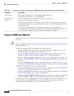
Страница 139: ...ins four fiber ports and link activity and bypass LEDs Use the following table to understand link and activity LEDs of the fiber interfaces Table 7 44 Copper Link Activity LEDs Status Description Both LEDs off The interface does not have link and is not in bypass mode Link amber The speed of the traffic on the interface is 10Mb or 100Mb Link green The speed of the traffic on the interface is 1Gb A...

Страница 140: ...he light is always on Table 7 47 Fiber Bypass LEDs Status Description Off The interface does not have link and is not in bypass mode Steady green The interface has link and is passing traffic Steady amber The interface has been intentionally brought down Blinking amber The interface is in bypass mode that is it has failed open Table 7 48 1000BASE SX NetMod Optical Parameters Parameter 1000BASE SX ...

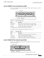
Страница 141: ...e interface A blinking light indicates the interface has activity No light indicates there is no activity Bottom For an inline interface A light indicates the interface has activity No light indicates there is no activity For a passive interface the light is always on Table 7 50 Fiber Bypass LEDs Status Description Off The interface does not have link and is not in bypass mode Steady green The int...

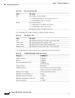
Страница 142: ... 860 nm 850 nm typical 85 ft 26 m to 108 ft 33 m for 62 5 µm 125 µm fiber modal BW 160 to 200 respectively 216 ft 66 m to 269 ft 82 m for 50 µm 125 µm fiber modal BW 400 to 500 respectively Distances to 980 ft 300 m are available with higher quality OM3 fiber Minimum distances all 6ft 2 m 1270 1355 nm 1310 nm typical 6 ft to 6 2 miles 2 m to 10 km for 9 µm 125 µm fiber Transmitter wavelength 840 8...

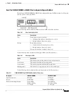
Страница 143: ...ctivity The light flashes when the interface has activity If dark there is no activity Bottom link The light is on when the interface has link If dark there is no link Table 7 53 Fiber Bypass LED Status Description Off The interface pair does not have link and is not in bypass mode or has no power Steady green The interface pair has link and is passing traffic Steady amber The interface has been i...

Страница 144: ...fiber ports and link and activity LEDs Use the following table to understand the link and activity LEDs on the fiber interfaces Minimum average launch power 7 8 dBm Maximum average power at receiver 2 4 dBm Receiver sensitivity 9 5 dBm Table 7 54 40GBASE SR4 NetMod Optical Parameters continued Parameter 40GBASE SR4 Table 7 55 Non Bypass Copper Link Activity LEDs Status Description Both LEDs Off Th...

Страница 145: ... Fiber Link Activity LEDs Status Description Top Activity For an inline or passive interface the light flashes when the interface has activity If dark there is no activity Bottom Link For an inline interface the light is on when the interface has link If dark there is no link For a passive interface the light is always on Table 7 57 1000BASE SX NetMod Optical Parameters Parameter 1000BASE SX Optic...

Страница 146: ...ameters Parameter 10GBASE MMSR 10GBASE SMLR Optical connectors LC duplex LC duplex Bit rate 10 000Gbps 10 000Gbps Baud rate encoding tolerance 10 3125Gbps 64 66b encoding 100 ppm 10 3125Gbps 64 66b encoding 100 ppm Optical interface Multimode Single mode only Operating distance 840 860 nm 850 nm typical 85 ft 26 m to 108 ft 33 m for 62 5 µm 125 µm fiber modal BW 160 to 200 respectively 216 ft 66 m...

Страница 147: ...following 8000 Series stacked configurations Firepower 8260 8270 and 8290 Firepower and AMP 8360 8370 and 8390 You can use the following table to understand the stacking LEDs Table 7 60 Stacking LEDs Status Description Top Indicates activity on the interface A blinking light indicates there is activity on the interface No light indicates there is no activity Bottom Indicates whether the interface ...

Страница 148: ...7 42 Firepower 7000 and 8000 Series Installation Guide Chapter 7 Hardware Specifications Firepower 8000 Series Devices ...

Страница 149: ...iliarize yourself with the expected behavior of the system during the restore process Configuration and Event Backup Guidelines Before you begin the restore process Cisco recommends that you delete or move any backup files that reside on your appliance then back up current event and configuration data to an external location Restoring your appliance to factory defaults results in the loss of almos...

Страница 150: ...he appliance which is useful for rack mounted appliances connected to a KVM keyboard video and mouse switch If you have a KVM that is remote accessible you can restore appliances without having physical access Serial Connection Laptop You can use a rollover serial cable also known as a NULL modem cable or a Cisco console cable to connect a computer to the appliance See the hardware specifications ...

Страница 151: ...he Firepower Management Center Configuration Guide For your convenience you can install system software and intrusion rule updates as part of the restore process For example you could restore a device to Version 6 0 and also update the device to Version 6 0 0 1 as part of that process Keep in mind that only Management Centers require rule updates To obtain the restore ISO and other update files St...

Страница 152: ...hapter explain how to restore an appliance without powering it down However if you need to power down for any reason use the appliance s web interface the system shutdown command from the CLI on a Firepower device or the shutdown h now command from an appliance s shell sometimes called expert mode Starting the Restore Utility Using KVM or Physical Serial Port Access Admin For Firepower devices Cis...

Страница 153: ...e for the restore utility s interactive menu For a keyboard and monitor connection type 0 and press Enter For a serial connection type 1 and press Enter If you do not select a display mode the restore utility defaults to the standard console after 30 seconds Unless this is the first time you have restored the appliance to this major version the utility automatically loads the last restore configur...

Страница 154: ...s may take a long time to finish When you see the BIOS boot options press Tab slowly and repeatedly to prevent the appliance from booting the currently installed version of the system until the LILO boot prompt appears For example LILO 22 8 boot System 5 4 System_Restore Step 4 At the boot prompt start the restore utility by typing System_Restore The boot prompt appears after the following choices...

Страница 155: ...ew version of the system software If this is your second pass or if the restore utility automatically loaded the restore configuration you want to use you can start with menu option 4 Downloading the ISO and Update Files and Mounting the Image page 8 11 However Cisco recommends you double check the settings in the restore configuration before proceeding Table 8 1 Restore Menu Options Option Descri...

Страница 156: ...store utility is to identify the management interface on the appliance you want to restore so that the appliance can communicate with the server where you copied the ISO and any update files If you are using LOM remember that the management IP address for the appliance is not the LOM IP address To identify the appliance s management interface Step 1 From the main menu select 1 IP Configuration Ste...

Страница 157: ...r your FTP server for more information Step 3 Use the series of pages presented by the restore utility to provide the necessary information for the protocol you chose as described in Table 8 2 on page 8 9 If your information was correct the appliance connects to the server and displays a list of the Cisco ISO images in the location you specified Table 8 2 Information Needed to Download Restore Fil...

Страница 158: ...o update the appliance during the restore process you can update later using the system s web interface For more information see the release notes for the update you want to install as well as the Updating System Software chapter in the Firepower Management Center Configuration Guide To install updates as part of the restore process Step 1 From the main menu select 3 Select Patches Rule Updates Th...

Страница 159: ...O image you are ready to invoke the restore process If you are restoring an appliance to a different major version from the version currently installed on the appliance a two pass restore process is required The first pass updates the operating system and the second pass installs the new version of the system software First Pass of Two Changing Major Versions Only When restoring an appliance to a ...

Страница 160: ...Unless this is the first time you have restored the appliance to this major version the utility automatically loads the last restore configuration you used To continue confirm the settings in a series of pages Step 6 Press Enter to confirm the copyright notice What to do Next Begin the second pass of the process starting with Using the Interactive Menu to Restore an Appliance page 8 6 Second or On...

Страница 161: ...ion to use if you need to restore a Firepower device again Although the restore utility automatically saves the last configuration used you can save multiple configurations which include network information about the management interface on the appliance see Identifying the Appliance s Management Interface page 8 8 the location of the restore ISO image as well as the transport protocol and any cre...

Страница 162: ...ing the Image page 8 11 Next Steps Restoring your appliance to factory default settings results in the loss of almost all configuration and event data on the appliance including bypass configurations for devices deployed inline For more information see Traffic Flow During the Restore Process page 8 1 After you restore an appliance you must complete an initial setup process If you did not delete th...

Страница 163: ...or monitoring conditions such as fan speed and temperature The syntax of LOM commands depends on the utility you are using but LOM commands generally contain the elements listed in the following table Therefore for IPMItool ipmitool I lanplus H IP_address U username command Or for ipmiutil ipmiutil command V4 J3 N IP_address U username P password Note that the chassis power off and chassis power c...

Страница 164: ...g an IPMI Utility page 8 17 Enabling LOM and LOM Users Access Admin Before you can use LOM to restore an appliance you must enable and configure the feature You must also explicitly grant LOM permissions to users who will use the feature You configure LOM and LOM users on a per appliance basis using each appliance s local web interface That is you cannot use the Management Center to configure LOM ...

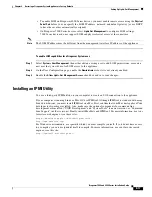
Страница 165: ...tion page enable the Administrator role if it is not already enabled Step 3 Enable the Allow Lights Out Management Access check box and save your changes Installing an IPMI Utility You use a third party IPMI utility on your computer to create an SOL connection to the appliance If your computer is running Linux or Mac OS use IPMItool Although IPMItool is standard with many Linux distributions you m...

Страница 166: ...8 18 Firepower 7000 and 8000 Series Installation Guide Chapter 8 Restoring a Firepower System Appliance to Factory Defaults Setting Up Lights Out Management ...

Страница 167: ...scribed in GR 1089 CORE Issue 4 and require isolation from the exposed OSP cabling The addition of the primary protectors is not sufficient protection to connect these interfaces metallically to OSP wiring Static Control Caution Electrostatic discharge control procedures such as using grounded wrist straps and an ESD work surface must be in place before unpacking installing or moving the appliance...

Страница 168: ...ull rating of the appliance Voltage The power supply works with 100VAC to 240VAC nominal 90VAC to 264VAC maximum Use of voltages outside this range may cause damage to the appliance Current The labeled current rating is 2A maximum over the full range Appropriate wire and breakers must be used to reduce the potential for fire Frequency Range The frequency range of the AC power supply is 47 Hz to 63...

Страница 169: ... a single fault The size of the ground wire should be equal to the current of the breaker used to protect the circuit See Current page A 2 Bare conductors must be coated with antioxidant before crimp connections are made Only copper cables can be used for grounding purposes Firepower 71xx Family Appliances This section describes the power requirements for Firepower 7110 and 7120 GERY 1U 8 AC Firep...

Страница 170: ...liance This configuration provides for circuit failure and power supply failure Example Each supply is attached to a different 220V circuit Each circuit must be capable of supplying 5A as stated on the label Same Circuit Installation If the same circuit is used to feed both supplies then the power rating of one supply applies to the whole box This configuration only provides protection from a powe...

Страница 171: ...erminals You must use UL Approved terminals for the ground connection Ring terminals with a clearance hole for 4mm or 8 studs may be used For 10 12 AWG wire Tyco 34853 is recommended This is a UL approved ring terminal with a hole for a 8 stud Ground Wire Requirements The ground wire must be sized sufficiently to handle the current of the circuit in case of a single fault The size of the ground wi...

Страница 172: ...nt ratings for each supply are listed on the label on the appliance Use an external Surge Protection Device at the input of the network equipment where the Firepower System is to be installed Separate Circuit Installation If separate circuits are used each one must be rated the full rating of the appliance This configuration provides for circuit failure and power supply failure Example Each supply...

Страница 173: ...each power supply to run the entire appliance The voltage and current ratings for each supply are listed on the label on the appliance Use an external Surge Protection Device at the input of the network equipment where the Firepower System is to be installed Separate Circuit Installation If separate circuits are used each circuit must be rated to the full rating of the appliance This configuration...

Страница 174: ...d The circuit breaker must meet the following requirements UL Recognized CSA Approved Recommended VDE Approved Recommended Support the maximum load 20A Support the installation voltage 40V to 72VDC as required by the power supply Rated for DC use A recommended breaker is Airpax IELK1 1 72 20 0 01 V The terminal option used will depend on the installation This breaker is a single pole 20A breaker w...

Страница 175: ...C circuits see AC Current page A 6 For DC currents see DC Current page A 8 Bare conductors must be coated with antioxidant before crimp connections are made Only copper cables can be used for grounding purposes DC Supplies The DC power supplies have additional ground connections on each supply This allows the hot swappable supply to be connected to power return and ground so that it may be safely ...

Страница 176: ...he appliance Use an external Surge Protection Device at the input of the network equipment where the Firepower System is to be installed Separate Circuit Installation If separate circuits are used each one must be rated the full rating of the appliance This configuration provides for circuit failure and power supply failure Example Each supply is attached to a different 220V circuit Each circuit m...

Страница 177: ... each power supply to run the entire appliance The voltage and current ratings for each supply are listed on the label on the appliance Use an external Surge Protection Device at the input of the network equipment where the Firepower System is to be installed Separate Circuit Installation If separate circuits are used each circuit must be rated to the full rating of the appliance This configuratio...

Страница 178: ...ed The circuit breaker must meet the following requirements UL Recognized CSA Approved Recommended VDE Approved Recommended Support the maximum load 20A Support the installation voltage 40V to 72VDC as required by the power supply Rated for DC use A recommended breaker is Airpax IELK1 1 72 20 0 01 V The terminal option used will depend on the installation This breaker is a single pole 20A breaker ...

Страница 179: ...qual to the current of the breaker used to protect the circuit For AC circuits see AC Current page A 6 For DC currents see DC Current page A 8 Bare conductors must be coated with antioxidant before crimp connections are made Only copper cables can be used for grounding purposes DC Supplies The DC power supplies have additional ground connections on each supply This allows the hot swappable supply ...

Страница 180: ...current ratings for each supply are listed on the label on the appliance Use an external Surge Protection Device at the input of the network equipment where the Firepower System is to be installed Separate Circuit Installation If separate circuits are used each one must be rated the full rating of the appliance This configuration provides for circuit failure and power supply failure Example Each s...

Страница 181: ...r to each power supply to run the entire appliance The voltage and current ratings for each supply are listed on the label on the appliance Use an external Surge Protection Device at the input of the network equipment where the Firepower System is to be installed Separate Circuit Installation If separate circuits are used each circuit must be rated to the full rating of the appliance This configur...

Страница 182: ...ovided The circuit breaker must meet the following requirements UL Recognized CSA Approved Recommended VDE Approved Recommended Support the maximum load 20A Support the installation voltage 40V to 72VDC as required by the power supply Rated for DC use A recommended breaker is Airpax IELK1 1 72 20 0 01 V The terminal option used will depend on the installation This breaker is a single pole 20A brea...

Страница 183: ... is a UL approved ring terminal with a hole for a 8 stud Ground Wire Requirements The ground wire must be sized sufficiently to handle the current of the circuit in case of a single fault The size of the ground wire should be equal to the current of the breaker used to protect the circuit For AC circuits see AC Current page A 14 For DC currents see DC Current page A 16 Bare conductors must be coat...

Страница 184: ...A 18 Firepower 7000 and 8000 Series Installation Guide Appendix A Power Requirements for Firepower Devices Firepower and AMP 83xx Family Appliances ...

Страница 185: ...eight SFP transceivers Figure B 1 3D71x5 and AMP7150 Front View 3D71x5 and AMP7150 SFP Sockets The eight SFP sockets are numbered from 5 through 12 in a vertical pattern and oriented in a tab to center configuration the upper row faces up and the lower row faces down The accompanying LEDs to the left of the sockets display information on activity and link for each interface See Table 7 28Firepower...

Страница 186: ...ual switches virtual routers and some access control policies For a passive deployment you can use any combination of transceivers in up to eight sockets to monitor up to eight network segments For an inline deployment you can use any combination copper fiber or mixed of transceivers in vertically sequential sockets 5 and 6 7 and 8 9 and 10 or 11 and 12 to monitor up to four network segments Use t...

Страница 187: ... the change Removing an SFP Transceiver Use appropriate electrostatic discharge ESD procedures when removing the transceiver Avoid touching the contacts at the rear and keep the contacts and ports free of dust and dirt To remove an SFP transceiver Step 1 Disconnect all cables from the transceiver you want to remove from the device Step 2 Using your fingers gently pull the bale of the transceiver a...

Страница 188: ...B 4 Firepower 7000 and 8000 Series Installation Guide Appendix B Using SFP Transceivers in 3D71x5 and AMP7150 Devices Removing an SFP Transceiver ...

Страница 189: ...an use the modules in the following slots Firepower 81xx Family page C 1 Firepower 82xx Family and 83xx Family page C 2 After you insert the modules into your device see the following sections for more information on using the modules For information on configuring the sensing interfaces see Identifying the Sensing Interfaces page 4 3 For information on using the stacking module see Using Devices ...

Страница 190: ...mary Device Stacking Configuration Considerations Configure the modules as follows for stacked devices Install NetMods on the primary device only Install one stacking module on the primary device for each stacked secondary device and one stacking module on each secondary device Figure C 3 Firepower 82xx Family and 83xx Family Secondary Device Included Items Your module assembly kit includes a T8 T...

Страница 191: ...pass NetMod page 7 38 quad port 10GBASE MMSR or SMLR fiber non bypass NetMod For more information see Quad Port 10GBASE MMSR or SMLR Fiber Non Bypass NetMod page 7 39 Caution The quad port 10GBASE fiber non bypass NetMod contains non removable small form factor pluggable SFP transceivers Any attempt to remove the SFPs can damage the module stacking module For more information see Stacking Module p...

Страница 192: ... module parts Identify the slots where you want to install your NetMods Tip You can insert the NetMod into any available compatible slot Identify the correct slots for your stacking modules See Using Devices in a Stacked Configuration page 4 13 Firepower 8140 slot 3 Firepower 8250 8260 and 8350 8360 primary slot slot 5 Firepower 8270 and 8370 primary slots slots 5 and 1 Firepower 8290 and 8390 pri...

Страница 193: ...ving modules Removing a Module or Slot Cover Use proper electrostatic discharge ESD practices such as wearing wrist straps and using an ESD work surface when handling the modules Store unused modules in an ESD bag or box to prevent damage To remove a module or slot cover Step 1 Remove and reserve the T8 Torx screw from the lever of the module using the included screwdriver Step 2 Pull the lever aw...

Страница 194: ... a Module or Slot Cover page C 5 for more information To insert a module or slot cover Step 1 Remove and reserve the T8 Torx screw from the lever of the module using the included screwdriver Step 2 Pull the lever away from the module to open the latch The near end of the latch is visible The far end of the latch is inside the module Step 3 Insert the module into the slot until the far end of the l...

Страница 195: ...ignment Step 4 Push the lever toward the module so that the latch engages and pulls the module into the slot Caution Do not use excessive force If the latch does not engage remove and realign the module then try again Step 5 Press firmly on the screw hole to push the lever fully against the module to secure the latch The lever is fully against the module and the module is flush with the chassis ...

Страница 196: ...power 7000 and 8000 Series Installation Guide Appendix C Inserting and Removing Firepower 8000 Series Modules Inserting a Module or Slot Cover Step 6 Insert and tighten the reserved T8 Torx screw into the lever ...

Страница 197: ...andom character and verify Please refer to the DoD document for additional constraints Caution Scrubbing your hard drive results in the loss of all data on the appliance which is rendered inoperable You scrub the hard drive using an option in the interactive menu described in Using the Interactive Menu to Restore an Appliance page 8 6 To scrub the hard drive Access Admin Step 1 Follow the instruct...

Страница 198: ...D 2 Firepower 7000 and 8000 Series Installation Guide Appendix D Scrubbing the Hard Drive Scrubbing the Contents of the Hard Drive ...

Страница 199: ...tions Tip Save all packing materials and include all reference material and power cords when repackaging the appliance Before You Begin Before preconfiguring the appliance collect the network settings licenses and other pertinent information for the staging location and the target location Tip It can be helpful to create a spreadsheet to manage this information at the staging location and the targ...

Страница 200: ...ce could lose the IP address assigned to it by the DHCP server Because of this Cisco recommends you configure the Firepower 7050 BMC with a static IP address Alternately you can disconnect the network cable and reconnect it or remove and restore power to the device to force renegotiation of the link If you want to register a device to a Management Center you need the following information the name...

Страница 201: ...erface on its managing Management Center See Registering a Firepower Device to a Management Center Using the CLI page 5 4 and Working In NAT Environments in the Firepower Management Center Configuration Guide Add licenses during the initial setup If you do not add licenses at that time any devices you register during initial setup are added to the Firepower Management Center as unlicensed you must...

Страница 202: ...lete the device from the Management Center This prevents the device from looking for the UUID of the original Management Center when you register the device to a different Management Center at the target location To delete a device from the Management Center Step 1 On the Management Center Select Devices Device Management Step 2 Next to the device you want to delete click the delete icon When prom...

Страница 203: ...e if your Protection license is valid and enabled for 100 managed devices deleting the license removes protection capabilities from all 100 devices Step 3 Confirm that you want to delete the license The license is deleted Powering Down the Appliance Access Admin Use the following procedures to power down the appliance safely before disconnecting the power supply To power down a Firepower device St...

Страница 204: ...e current password for your appliance The initial setup at the staging location prompts you to change your password See the configuration information provided by the staging location for the new password Confirm that the network settings are correct See Initial Setup Page Firepower Devices page 5 5 Confirm that the correct communication ports are functioning properly See the documentation for your...

Отзывы: