


3-2
Firepower 7000 and 8000 Series Installation Guide
Chapter 3 Deploying Firepower Managed Devices
Understanding Sensing Interfaces
Understanding Sensing Interfaces
The sections that follow describe how different sensing interfaces affect the capabilities of the Firepower
System. In addition to passive and inline interfaces, you can also have routed, switched, and hybrid
interfaces.
Sensing interfaces are located on the front of the device. To identify your sensing interfaces, see
Identifying the Sensing Interfaces, page 4-3
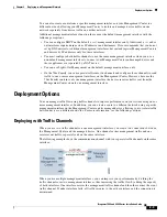
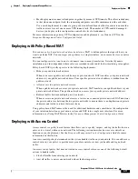
Passive Interfaces
You can configure a passive deployment to monitor traffic flowing across a network using a switch
SPAN, virtual switch, or mirror port, allowing traffic to be copied from other ports on the switch. Passive
interfaces allow you to inspect traffic within the network without being in the flow of network traffic.
When configured in a passive deployment, the system cannot take certain actions such as blocking or
shaping traffic. Passive interfaces receive all traffic unconditionally and do not retransmit received
traffic.
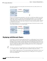
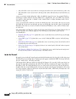
Inline Interfaces
You configure an inline deployment transparently on a network segment by binding two ports together.
Inline interfaces allow you to install a device in any network configuration without the configuration of
adjacent network devices. Inline interfaces receive all traffic unconditionally, then retransmit all traffic
received on these interfaces except traffic explicitly dropped. You must assign a pair of inline interfaces
to an inline set before they can handle traffic in an inline deployment.
Note
If you configure an interface as an inline interface, the adjacent port on its NetMod automatically
becomes an inline interface as well to complete the pair.
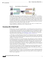
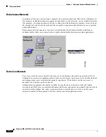
Configurable bypass inline sets allow you to select how your traffic is handled if your hardware fails
completely (for example, the device loses power). You may determine that connectivity is critical on one
network segment, and, on another network segment, you cannot permit uninspected traffic. Using
configurable bypass inline sets, you can manage the traffic flow of your network traffic in one of the
following ways:
•
Bypass
: an interface pair configured for bypass allows all traffic to flow if the device fails. The
traffic bypasses the device and any inspection or other processing by the device. Bypass allows
uninspected traffic across the network segment, but ensures that the network connectivity is
maintained.
•
Non-bypass
: an interface pair configured for non-bypass stops all traffic if the device fails. Traffic
that reaches the failed device does not enter the device. Non-bypass does not permit traffic to pass
uninspected, but the network segment loses connectivity if the device fails. Use non-bypass
interfaces in deployment situations where network security is more important than loss of traffic.
Configure the inline set as bypass to ensure that traffic continues to flow if your device fails. Configure
the inline set as non-bypass to stop traffic if the device fails. Note that reimaging resets Firepower
devices in bypass mode to a non-bypass configuration and disrupts traffic on your network until you
reconfigure bypass mode. For more information, see
Traffic Flow During the Restore Process, page 8-1
.


