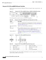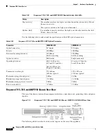
7-4
Firepower 7000 and 8000 Series Installation Guide
Chapter 7 Hardware Specifications
Firepower 7000 Series Devices
Sensing Interfaces
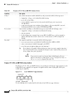
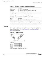
The Firepower 70xx Family appliances are delivered with eight copper interfaces, each with
configurable bypass capability.
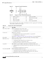
Figure 7-3
Eight-Port 1000BASE-T Copper Interfaces
Use the following table to understand the activity and link LEDs on the copper interfaces.
Use the following table to understand bypass LEDs on the copper interfaces.
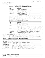
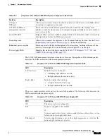
The 10/100/1000 management interface is located on the front of the appliance. The following table
describes the LEDs associated with the management interface.
Table 7-5
Firepower 70xx Family Copper Link/Activity LEDs
Status
Description
Both LEDs off
The interface does not have link.
Link amber
The speed of the traffic on the interface is 10Mb or 100Mb.
Link green
The speed of the traffic on the interface is 1Gb.
Activity blinking green
The interface has link and is passing traffic.
Table 7-6
Firepower 70xx Family Copper Bypass LEDs
Status
Description
Off
The interface pair is not in bypass mode or has no power.
Steady green
The interface pair is ready to enter bypass mode.
Steady amber
The interface pair has been placed in bypass mode intentionally, or has
entered bypass mode gracefully, and is not inspecting traffic.
Blinking amber
The interface pair has unexpectedly entered bypass mode; that is, it has failed
open.
Table 7-7
Firepower 70xx Family Management Interface LEDs
LED
Description
Left (link)
7010/20/30
Indicates whether the link is up. If the light is on, the link is
up. If the light is off, there is no link.
7050
For 10Mbps links, the link light does not illuminate. Link
status is shared with the right (activity) LED.


