7-18
Firepower 7000 and 8000 Series Installation Guide
Chapter 7 Hardware Specifications
Firepower 7000 Series Devices
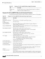
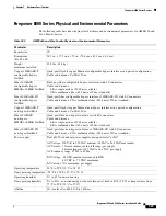
Use the following table to understand the specifications of the SFP optical transceivers.
Firepower 7115, 7125, and AMP7150 Chassis Rear View
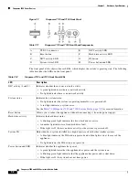
The rear of the chassis contains the management interface, connection ports, grounding studs, and power
supplies.
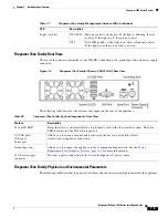
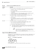
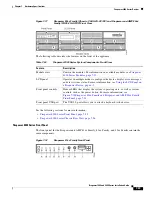
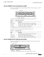
Figure 7-15
Firepower 7115, 7125, and AMP7150 (Chassis: GERY-1U-8-4C8S-AC) Rear View
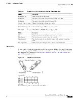
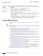
The following table describes the features that appear on the rear of the appliance.
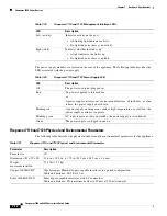
Table 7-28
Firepower 7115, 7125, and AMP7150 SFP Socket Activity/Link LEDs
Status
Description
Top (activity)
For an inline interface: the light is on when the interface has activity. If dark,
there is no activity.
For a passive interface: the light is non-functional.
Bottom (link)
For an inline or passive interface: the light is on when the interface has link.
If dark, there is no link.
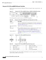
Table 7-29
Firepower 7115, 7125, and AMP7150 SFP Optical Parameters
Parameter 1000BASE-SX
1000BASE-LX
Optical connectors
LC duplex
LC duplex
Bit rate
1000Mbps
1000Mbps
Baud rate/encoding/tolerance
1250Mbps
8b/10b encoding
1250Mbps
8b/10b encoding
Optical interface
Multimode
Single mode only
Operating distances
656 ft (200 m) for
62.5 µm/125 µm fiber
1640 ft (500 m) for
50 µm/125 µm fiber
6.2 miles (10 km) for
9 µm/125 µm fiber
Transmitter wavelength
770-860 nm
(850 nm typical)
1270-1355 nm
(1310 nm typical)
Maximum average launch power
0 dBm
-3 dBm
Minimum average launch power
-9.5 dBm
-11.5 dBm
Maximum average power at receiver
0 dBm
-3 dBm
Receiver sensitivity
-17 dBm
-19 dBm


