


7-12
Firepower 7000 and 8000 Series Installation Guide
Chapter 7 Hardware Specifications
Firepower 7000 Series Devices
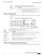
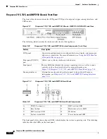
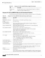
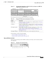
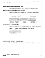
The power supply modules are located on the rear of the appliance. The following table describes the
LED associated with the power supply.
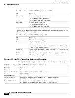
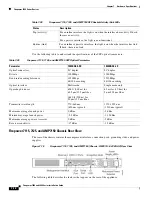
Firepower 7110 and 7120 Physical and Environmental Parameters
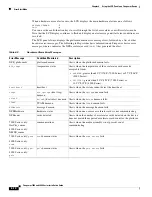
The following table describes the physical attributes and the environmental parameters for the appliance.
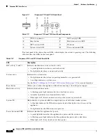
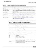
Table 7-19
Firepower 7110 and 7120 Management Interface LEDs
LED
Description
Left (activity)
Indicates activity on the port:
•
A blinking light indicates activity.
•
No light indicates there is no activity.
Right (link)
Indicates whether the link is up:
•
A light indicates the link is up.
•
No light indicates there is no link.
Table 7-20
Firepower 7110 and 7120 Power Supply LED
LED
Description
Off
The power cord is not plugged in.
Red
No power supplied to this module.
or
A power supply critical event, such as module failure, a blown fuse, or a fan
failure; the power supply shuts down.
Blinking red
A power supply warning event, such as high temperature or a slow fan; the
power supply continues to operate.
Blinking green
AC input is present; volts on standby, the power supply is switched off.
Green
The power supply is plugged in and on.
Table 7-21
Firepower 7110 and 7120 Physical and Environmental Parameters
Parameter
Description
Form factor
1U
Dimensions (D x W x H)
21.6 in. x 19.0 in. x 1.73 in. (54.9 cm x 48.3 cm x 4.4 cm)
Weight
maximum installed
27.5 lbs (12.5 kg)
Copper 1000BASE-T
Gigabit copper Ethernet bypass-capable interfaces in a paired configuration
Cable and distance: Cat5E at 50 m
Fiber 1000BASE-SX
Fiber bypass-capable interfaces with LC connectors
Cable and distance: SX is multimode fiber (850 nm) at 550 m (standard)


