background image

S e n d   d o c u m e n t a t i o n   c o m m e n t s   t o   m d s f e e d b a c k - d o c @ c i s c o . c o m .

D-24

Cisco MDS 9500 Series Hardware Installation Guide

OL-17467-02

Appendix D      Technical Specifications

    SFP and SFP+ Transceiver Specifications

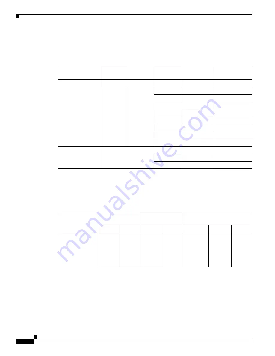
General Specifications for Cisco 8-Gbps Fibre Channel SFP+ Transceivers

Table D-28

 provides the general specifications for Cisco Fibre Channel SFP+ transceivers.

Environmental and Power Requirements for Cisco 8-Gbps Fibre Channel SFP+ Transceivers

Table D-29

 provides the power specification for the Cisco 8-Gbps Fibre Channel SFP+ transceivers.

Table D-28

General Specifications for Cisco 8-Gbps Fibre Channel SFP+ Transceivers

SFP

Wavelength 


(nanometer)

Fiber Type

Core Size


(micon)

Baud Rate
(GBd)

Cable Distance
(meter)

DS-SFP-FC8G-SW

850

MMF

62.5

2.125

150 m (492 ft)

62.5

4.250

70 m (230 ft)

62.5

8.500

21 m (69 ft)

50.0 (OM2)

2.125

300 m (984 ft)

50.0 (OM2)

4.250

150 m (492 ft)

50.0(OM2)

8.500

50 m (164 ft)

50. 0 (OM3)

2.125

500 m (1640 ft)

50. 0 (OM3)

4.250

380 m (1246 ft)

50. 0 (OM3)

8.500

150 m (492 ft)

DS-SFP-FC8G-LW

1310

SMF

9.0

2.125

6.2 miles (10 km)

9.0

4.250

6.2 miles (10 km)

9.0

8.500

6.2 miles (10 km)

Table D-29

Power Requirements Specification for Cisco 8-Gbps Fibre Channel SFP+ Transceivers 

SFP

Average Transmit 


Power (dBm)

Average Receive 


Power (dBm)

Fiber Loss Budget (dBm)

Maximum

Minimum

Maximum

Minimum

DS-SFP-FC8G-SW -1.3

-10 (2 
Gbps)


-9 (4 
Gbps)


-8.2 (8 
Gbps)

0

62.5 micron
s

50.0 
microns 
[OM2]

50.0 
microns 
[OM3]

Содержание Cisco mds 9216 - fabric switch

Страница 1: ... d o c c i s c o c o m Americas Headquarters Cisco Systems Inc 170 West Tasman Drive San Jose CA 95134 1706 USA http www cisco com Tel 408 526 4000 800 553 NETS 6387 Fax 408 527 0883 Cisco MDS 9500 Series Hardware Installation Guide October 2008 Text Part Number OL 17467 02 ...

Страница 2: ...r more of the following measures Turn the television or radio antenna until the interference stops Move the equipment to one side or the other of the television or radio Move the equipment farther away from the television or radio Plug the equipment into an outlet that is on a different circuit from the television or radio That is make certain the equipment and the television or radio are on circu...

Страница 3: ...e xix Intelligent Storage Networking Services Configuration Guides xix Troubleshooting and Reference xix Installation and Configuration Note xix Obtaining Documentation Obtaining Support and Security Guidelines xx C H A P T E R 1 Product Overview 1 1 Chassis 1 2 Cisco MDS 9513 Director 1 3 Cisco MDS 9509 Director 1 6 Cisco MDS 9506 Director 1 7 Backplane and Clock Modules 1 8 Cisco MDS Fibre Chann...

Страница 4: ...dule 1 35 12 port 4 Gbps Fibre Channel Switching Module 1 35 4 port 10 Gbps Fibre Channel Switching Module 1 36 LEDs on the Generation 2 Switching Modules 1 37 32 Port 2 Gbps Fibre Channel Switching Module 1 37 16 Port 2 Gbps Fibre Channel Switching Module 1 38 Switching Module Features 1 39 LEDs on the Generation 1 Switching Module 1 40 Services Modules 1 41 18 4 Port Multiservice Module 1 41 18 ...

Страница 5: ... 17 Proper Grounding Practices 2 17 Preventing Electrostatic Discharge Damage 2 19 Establishing the System Ground 2 22 Required Tools and Equipment 2 22 Grounding the Chassis 2 23 Starting Up the Switch 2 28 Connecting the Power Supplies 2 28 Providing Power to an AC Power Supply for the Cisco MDS 9513 Director 2 29 Providing Power to an AC Power Supply for the Cisco MDS 9509 and Cisco MDS 9506 Di...

Страница 6: ... a DC PEM 2 66 Removing an AC or DC Power Supply from the Cisco MDS 9506 Director 2 67 Installing an AC or DC Power Supply in the Cisco MDS 9506 Director 2 67 Removing and Installing Fan Modules 2 68 Removing a Front Fan Module on the Cisco MDS 9513 Director 2 69 Installing a Front Fan Module on the Cisco MDS 9513 Director 2 70 Removing the Crossbar Module Fan Tray 2 71 Installing the Crossbar Mod...

Страница 7: ...he MDS 9509 Director and MDS 9506 Director A 12 C H A P T E R B Connecting the Cisco MDS 9500 Series B 1 Preparing for Network Connections B 2 Connecting to the Console Port B 2 Connecting to the COM1 Port B 4 Connecting to the MGMT 10 100 1000 Ethernet Port B 6 Connecting to the MGMT 10 100 Ethernet Port B 7 Connecting to a Fibre Channel Port B 9 Removing and Installing X2 Transceivers B 9 Removi...

Страница 8: ... Post Telco Rack C 9 Installing the Shelf Bracket Kit into a Four Post EIA Rack C 10 Installing the Switch on the Rack Mount Support Brackets C 11 Installing the Switch on the Shelf Brackets C 12 Removing the Shelf Bracket Kit Optional C 12 Cisco MDS 9500 Shelf Bracket C 13 Rack Mounting Guidelines C 14 Before Installing the Shelf Brackets C 14 Required Equipment C 14 Installing the Cisco MDS 9500...

Страница 9: ...ers D 24 Environmental and Power Requirements for Cisco 8 Gbps Fibre Channel SFP Transceivers D 24 General Specifications for Cisco 4 Gbps Fibre Channel SFP Transceivers D 26 Environmental and Power Requirement for Cisco 4 Gbps Fibre Channel SFP Transceivers D 26 General Specifications for Cisco 2 Gbps Fibre Channel SFP Transceivers D 27 Environmental and Power Requirement for Cisco 2 Gbps Fibre C...

Страница 10: ...e COM1 Port to a Modem E 4 MGMT 10 100 1000 Ethernet Port E 4 MGMT 10 100 Ethernet Port E 6 Supported Power Cords and Plugs E 7 Power Cords E 7 Supported Plugs for 6000 W AC 2500 W AC and 1900 W AC Power Supplies E 9 Supported Plugs for the 4000 W AC Power Supply E 11 Jumper Power Cord E 11 Power Supply AC Power Cords E 12 AC Power Cord Illustrations E 13 A P P E N D I X F Site Planning and Mainte...

Страница 11: ...rs 48 autosensing 1 2 4 and 8 Gbps Fibre Channel ports and can be used in the Cisco MDS 9500 Series Switches 4 1 1b The 48 port 8 Gbps Fibre Channel Switching Module section on page 1 33 and the Technical Specifications section on page D 1 24 port 8 Gbps Fibre Channel switching module Added 24 port 8 Gbps Fibre Channel switching module The switching module offers 24 autosensing 1 2 4 and 8 Gbps Fi...

Страница 12: ... support 3 3 1a The 18 4 Port Multiservice Module section on page 1 41 18 4 port Multiservice MSM 18 4 module Added the Storage Media Encryption information 3 2 1 The 18 4 Port Multiservice Module section on page 1 41 18 4 port Multiservice MSM 18 4 module Added the new 18 4 port Multiservice MSM 18 4 module 3 2 1 The 18 4 Port Multiservice Module section on page 1 41 and the Technical Specificati...

Страница 13: ...odule Added 12 port 4 Gbps Fibre Channel switching module The switching module can be used in any of the Cisco MDS 9500 Series chassis and in the Cisco MDS 9216i and 9216A Switches 3 0 1 The 12 port 4 Gbps Fibre Channel Switching Module section on page 1 35 and the Technical Specifications section on page D 1 4 port 10 Gbps Fibre Channel switching module Added 4 port 10 Gbps Fibre Channel switchin...

Страница 14: ...iSCSI and Fibre Channel capability in a multiprotocol module 2 0 1b The 14 2 Port Multiprotocol Services Module section on page 1 44 Clock module installation Added installation procedure for clock modules Not release specific The Removing and Installing Clock Modules section on page 2 76 9500 Shelf Kit Added optional shelf bracket kit for the Cisco MDS 9509 Director Not release specific The Cisco...

Страница 15: ...pport for connecting the console port on the Cisco MDS 9500 Series to a modem 1 2 2a The Connecting to the Console Port section on page B 2 COM1 port to modem Connection Added support for connecting the COM1 port on the Cisco MDS 9500 Series to a modem 1 2 1a The Connecting to the COM1 Port section on page B 4 Gigabit Ethernet and CWDM SFP transceivers Added support for Gigabit Ethernet Fibre Chan...

Страница 16: ...Se n d d o c u m e n t a t i o n c o m m e n t s t o m d s f e e d b a ck d o c c i s c o c o m xiv Cisco MDS 9500 Series Hardware Installation Guide OL 17467 02 New and Changed Information ...

Страница 17: ... and its components Chapter 2 Installing the Cisco MDS 9500 Series Describes how to install the Cisco MDS 9500 Series including installing the chassis modules CompactFlash card power supplies and fan assembly Chapter B Connecting the Cisco MDS 9500 Series Describes how to connect the Cisco MDS 9500 Series including the modules Appendix A Migrating to Generation 3 8 Gbps Fibre Channel Switching Mod...

Страница 18: ... on any equipment be aware of the hazards involved with electrical circuitry and be familiar with standard practices for preventing accidents Use the statement number provided at the end of each warning to locate its translation in the translated safety warnings that accompanied this device Statement 1071 Waarschuwing Dit waarschuwingssymbool betekent gevaar U verkeert in een situatie die lichamel...

Страница 19: ... incidenti La traduzione delle avvertenze riportate in questa pubblicazione si trova nel documento Regulatory Compliance and Safety Information Conformità alle norme e informazioni sulla sicurezza che accompagna questo dispositivo Advarsel Dette varselsymbolet betyr fare Du befinner deg i en situasjon som kan føre til personskade Før du utfører arbeid på utstyr må du vare oppmerksom på de faremome...

Страница 20: ...bility Support Matrix Cisco MDS Storage Services Module Interoperability Support Matrix Cisco MDS NX OS Release Compatibility Matrix for Storage Service Interface Images Regulatory Compliance and Safety Information Regulatory Compliance and Safety Information for the Cisco MDS 9000 Family Hardware Installation Cisco MDS 9124 Multilayer Fabric Switch Quick Start Guide Cisco MDS 9500 Series Hardware...

Страница 21: ...ration Guide Cisco MDS 9000 Family Command Reference Intelligent Storage Networking Services Configuration Guides Cisco MDS 9000 Family Data Mobility Manager Configuration Guide Cisco MDS 9000 Family Storage Media Encryption Configuration Guide Cisco MDS 9000 Family Secure Erase Configuration Guide For Cisco MDS 9500 and 9200 Series Troubleshooting and Reference Cisco MDS 9000 Family Troubleshooti...

Страница 22: ...ce request and gathering additional information see the monthly What s New in Cisco Product Documentation which also lists all new and revised Cisco technical documentation at http www cisco com en US docs general whatsnew whatsnew html Subscribe to the What s New in Cisco Product Documentation as a Really Simple Syndication RSS feed and set content to be delivered directly to your desktop using a...

Страница 23: ...rector Redundant Supervisor 2 modules with associated integrated crossbar modules for the Cisco MDS 9509 and 9506 Directors Redundant Supervisor 1 modules with dual switching fabrics for the Cisco MDS 9509 and 9506 Directors Optional hot swappable switching or services modules Switching module port interfaces that support field replaceable hot swappable form factor pluggable X2 transceivers Switch...

Страница 24: ...2 module DS X9302 14K9 8 port IP Storage Services IPS 8 module DS X9308 SMIP 4 port IP Storage Services IPS 4 module DS X9304 SMIP Storage Services Module SSM DS X9032 SSM Advanced Services Module ASM DS X9032 SMV Caching Services Module CSM DS X9560 SMC This chapter includes the following sections Chassis page 1 2 Backplane and Clock Modules page 1 8 Cisco MDS Fibre Channel Switch for IBM Blade C...

Страница 25: ...les exist on both sides of the plane See Figure 1 1 The Cisco MDS 9513 Director supports the following Two Supervisor 2 modules that reside in slots 7 and 8 Switching and storage services modules See the Port Index Availability section on page 1 28 for possible configurations One hot swappable front panel fan tray with redundant individual fans Two power supplies located at the rear of the chassis...

Страница 26: ...Chassis Front Panel View The rear of the chassis supports two vertical redundant power supplies two clock modules two vertical redundant external crossbar modules and a variable speed fan tray with two individual fans located above the crossbar modules See Figure 1 2 1 Switching or services modules in slots 1 6 3 Switching or services modules in slots 9 13 2 Supervisor 2 modules in slots 7 and 8 4...

Страница 27: ...re Installation Guide OL 17467 02 Chapter 1 Product Overview Chassis Figure 1 2 Rear Panel 9513 Chassis 1 Power supplies 4 Air vent panels 2 crossbar module fans 5 Clock module1 1 Clock modules are located inside the air vent panel You must remove the air vent panel to access the clock modules 3 crossbar modules 144426 1 2 3 4 5 ...

Страница 28: ...port and a MGMT 10 100 Ethernet port on each module Slots 5 and 6 are reserved for the supervisor modules Seven slots for optional modules that can include up to seven switching modules or six IPS modules Two power supplies located in the front of the chassis The power supplies are redundant by default and can be configured to be combined if desired One hot swappable fan module with redundant fans...

Страница 29: ...the supervisor modules Four slots for optional modules that can include up to four switching modules or three IPS modules Two power supplies located in the back of the chassis The power supplies are redundant by default and can be configured to be combined if desired Two power entry modules PEMs in the front of the chassis for easy access to power supply connectors and switches One hot swappable f...

Страница 30: ...ver from one clock module to the other causing the system to reset automatically Cisco recommends that the failed clock module be replaced during a maintenance window See the Removing and Installing Clock Modules section on page 2 76 for information on replacing clock modules There are two LEDs per clock module Figure 1 5 shows the upper and lower LEDs Figure 1 5 Clock Module LEDs 1 Lower LEDs 2 U...

Страница 31: ... that are available in two configurations 7 internal ports and 3 external ports or 14 internal ports and 6 external ports Each port provides line rate performance up to 4 Gb without any performance loss for integrated features such as VSANs QoS or Network Address Translation NAT The Cisco MDS Fibre Channel Bladeswitch for IBM BladeCenter supports up to 16 VSANs per blade switch Each external port ...

Страница 32: ...ries Hardware Installation Guide OL 17467 02 Chapter 1 Product Overview Power Supplies Cisco MDS 9513 Power Supplies The Cisco MDS 9513 Director supports the 6000 W AC power supply AC input See Figure 1 6 Figure 1 6 Cisco MDS 9513 Power Supply 1 Power supply switch 3 Power Supply LEDs 2 AC power connection 144466 3 2 1 ...

Страница 33: ...than 85 V is good and power supply is functioning normally if two single 110 V or one single 220 V are connected Off Power supply is turned off or power is not connected INPUT 1 220VAC Green AC input is good at greater than 168 V and power supply should function normally Off AC input is 163 V or less or power is not connected INPUT 2 220VAC Green AC input is good at greater than 168 V and power su...

Страница 34: ...r supply AC input The 3000 W AC power supply requires 220 VAC to deliver 3000 W of power If powered with 110 VAC it delivers only 1400 W See Figure 1 8 2500 W AC power supply AC input and DC output The 2500 W AC power supply requires 220 VAC to deliver 2500 W of power If powered with 110 VAC it delivers only 1300 W See Figure 1 9 2500 W DC power supply DC input and DC output The 2500 W DC power su...

Страница 35: ... o m 1 13 Cisco MDS 9500 Series Hardware Installation Guide OL 17467 02 Chapter 1 Product Overview Power Supplies Figure 1 8 3000 W AC Power Supply for the Cisco MDS 9509 Director 1 AC power connection 4 Power supply LEDs 2 Power cable 5 Captive screws 3 Power supply switch 144986 1 2 3 4 5 5 ...

Страница 36: ...00 W AC Power Supply for the Cisco MDS 9509 Director Figure 1 10 2500 W DC Power Supply for the Cisco MDS 9509 Director 1 AC power connection 4 Captive screws 2 Cable retention device 5 Power supply LEDs 3 Power supply switch 94992 INPUT OK FAN OK OUTPUT FAIL I 0 4 3 1 5 2 1 Terminal block cover 4 Power supply switch 2 Power supply LEDs 5 Terminal block 3 Captive screw 99360 INPUT OK FAN OK OUTPUT...

Страница 37: ...r the label that indicates whether the power supply is AC or DC Figure 1 11 Cisco MDS 9506 Power Supply 1900 W AC or DC Table 1 3 describes the power supply LEDs for the Cisco MDS 9509 and 9506 Directors 1 Power supply LEDs 2 Captive screws IN PU T O K FA N O K O U TP U T FA IL 94996 1 2 Table 1 3 Power Supply LEDs for the Cisco MDS 9509 and 9506 Directors LED Status Description Input OK Green AC ...

Страница 38: ...s or power supply has failed Caution The Cisco MDS 9000 Family switches have internal temperature sensors that are capable of shutting down the system if the temperature at different points within the chassis exceed certain safety thresholds To be effective the temperature sensors require the presence of airflow therefore in the event a fan module is removed from the chassis the Cisco MDS 9000 Fam...

Страница 39: ...e Dual fabric configurations provide 1 4 Tbps speed with 160 Gbps full duplex bandwidth per switching module This integrated crossbar switching fabric is disabled when a Supervisor 2 module is installed in a Cisco MDS 9513 Director The Cisco MDS 9513 Director supports two external crossbar modules located at the rear of the chassis that handle this function For more information see the Crossbar Mo...

Страница 40: ...rvisor 2 has been replaced or restarted operation does not switch back to the original primary Supervisor 2 unless it is forced to switch back or another failure occurs Processor The Supervisor 2 module has a processor running at 1 4 GHz It contains a PowerPC class processor and offers the following memory specifications Port Interfaces The Supervisor 2 module provides the following port interface...

Страница 41: ...oftware images and configuration debugging and syslog information There is one LED that blinks when accessing this CompactFlash Caution Use only the CompactFlash devices that are certified for use with Cisco MDS 9000 switches and are formatted using Cisco MDS 9000 switches Using CompactFlash devices that are uncertified or are formatted using other platforms may result in errors LEDs on the Superv...

Страница 42: ...uring the initialization sequence An over temperature condition occurred a major threshold was exceeded during environmental monitoring System Green All chassis environmental monitors are reporting OK Orange One of the following occurred The power supply failed or the power supply fan failed Incompatible power supplies are installed The redundant clock failed Red The temperature of the supervisor ...

Страница 43: ...module Figure 1 14 Cisco MDS 9500 Series Supervisor 1 Module Control and Management The supervisor modules provide the following control and management features A redundant central arbiter that provides traffic control and access fairness A nondisruptive restart of a single failing process on the same supervisor A kernel service running on the supervisor module keeps track of the high availability...

Страница 44: ...ng module The Cisco MDS 9500 Series supports redundant supervisor modules Upon power up with slots 5 and 6 active the supervisors negotiate to determine which one is active and which is the standby supervisor Each supervisor exchanges its own status and updates the signal quality error SQE status periodically If the active supervisor becomes disabled the standby supervisor switches over to become ...

Страница 45: ...o MDS switches Using CompactFlash devices that are uncertified or are formatted using other platforms may result in errors LEDs on the Supervisor 1 Module The front panel on the Supervisor 1 module has the following LEDs Status LED System LED Active LED Power Management LED MGMT 10 100 Ethernet port LEDs at top of port Link LED on left Activity LED on right CompactFlash LED for external CompactFla...

Страница 46: ...ure condition occurred a major threshold was exceeded during environmental monitoring System1 1 The System and Pwr Mgmt LEDs on a redundant supervisor module are synchronized to the active supervisor module Green All chassis environmental monitors are reporting OK Orange One of the following occurs The power supply failed or the power supply fan failed Incompatible power supplies are installed The...

Страница 47: ...ve method where each switching module forwards traffic across both crossbar fabrics based on the intended destination The traffic load is shared across both crossbar modules Each crossbar fabric channel connects to a fabric interface ASIC on the switching modules through serial links on the midplane Each Supervisor 2 processor also has a 20 Gbps 40 Gbps FDX link to each crossbar fabric for partici...

Страница 48: ...The module is operational normal initialization sequence Orange One of the following occurs The module is booting or running diagnostics normal initialization sequence An over temperature condition occurred a minor threshold was exceeded during environmental monitoring Red One of the following occurs The diagnostic test failed The module is not operational because a fault occurred during the initi...

Страница 49: ...Channel switching module X X X X X X 24 port 4 Gbps Fibre Channel switching module X X X X X X 12 port 4 Gbps Fibre Channel switching module X X X X X X 4 port 10 Gbps Fibre Channel switching module X X X X X X 32 port 1 Gbps 2 Gbps Fibre Channel switching module X X X X X X 16 port 1 Gbps 2 Gbps Fibre Channel switching module X X X X X X 8 port Gigabit Ethernet IP Storage Services module X X X X ...

Страница 50: ...ystem assigns a block of port index numbers contiguously starting from the first port index reserved for the slot that the module is inserted in See Table 1 9 This Table 1 8 Port Index Allocation Module Physical Ports Port Indexes Allocated 48 port 8 Gbps Fibre Channel switching module 48 48 24 port 8 Gbps Fibre Channel switching module 24 24 4 44 port 8 Gbps Host Optimized Fibre Channel switching...

Страница 51: ... Allowed Alloted indices info range Total Index values 1 0 31 2 32 63 32 32 63 3 64 95 48 64 95 224 239 4 96 127 48 96 127 240 252 28 31 7 128 159 32 128 159 8 160 191 32 160 191 9 192 223 32 192 223 SU 253 255 3 253 255 Allowed range applicable only for Generation 1 modules Using any combination of modules that include a Generation 1 module and a Supervisor 2 module limits the port index availabi...

Страница 52: ...iguous In the range assigned to the given slot Start with the lowest value assigned to that slot Maximum 252 assignable port indexes available Generation 2 Indexes can be any available number in the range 0 252 Supervisor 2 Generation 1 Indexes must be contiguous but can be any available contiguous block in the range 0 252 Generation 2 Indexes can be any available number in the range 0 1020 if all...

Страница 53: ...s Configuration on a Cisco MDS 9509 Director Exceeded Slot No Modules in Cisco MDS 9509 Director Generation Physical Ports Port Indexes 1 18 port Fibre Channel and 4 port Gigabit Ethernet IP Multiservice module MSM 18 4 2 22 34 2 14 port Fibre Channel 2 port Gigabit Ethernet Multiprotocol Services MPS 14 2 module 1 16 22 3 8 port Gigabit Ethernet IP Storage Services module 1 8 32 4 4 port Gigabit ...

Страница 54: ...negotiate for speed at the other end of the link Each module has temperature sensors and an EEPROM that stores serial number and model number information The Fibre Channel port interfaces support hot swappable Fibre Channel SFP and SFP transceivers which can be short wavelength SWL or long wavelength LWL The port interfaces also support coarse wavelength division multiplexing CWDM and dense wavele...

Страница 55: ...sing 1 2 4 and 8 Gbps Fibre Channel ports and can be used in the Cisco MDS 9500 Series Switches The 24 port switching module can be configured in one of two operational modes shared bandwidth mode default and dedicated bandwidth mode Figure 1 18 shows a 24 port 8 Gbps Fibre Channel switching module The front panel connectors support standard modular SFP and SFP transceivers and the speed detection...

Страница 56: ...Cisco MDS 9500 Series chassis and in the Cisco MDS 9216i and 9216A Switches The 48 port switching module can be configured in one of two operational modes shared bandwidth mode default and dedicated bandwidth mode Figure 1 20 shows a 48 port 4 Gbps Fibre Channel switching module The front panel connectors support standard modular SFP and the speed detection is autosensing Figure 1 20 48 Port 4 Gbp...

Страница 57: ... Channel Switching Module 12 port 4 Gbps Fibre Channel Switching Module The 12 port 4 Gbps Fibre Channel switching module can be used in any of the Cisco MDS 9500 Series chassis and in the Cisco MDS 9216i and 9216A Switches The 12 port 4 Gbps switching module is a full rate mode module providing 12 SPF based Fibre Channel interfaces Each interface is capable of supporting full line rate operation ...

Страница 58: ...0 Gbps with no oversubscription This module can be used in any of the Cisco MDS 9500 Series chassis and in the Cisco MDS 9216i and 9216A Switches The module delivers a sustained data rate of up to 10 Gbps in each direction on all ports simultaneously and up to 80 Gbps of continuous aggregate bandwidth Figure 1 24 shows a 4 port 10 Gbps switching module The front panel connectors support standard m...

Страница 59: ...25 shows a 32 port switching module Table 1 13 LEDs for the Cisco MDS 9000 Family Generation 2 Fibre Channel Switching Modules LED Status Description Status Green All diagnostics pass The module is operational normal initialization sequence Orange One of the following occurs or occurred The module is booting or running diagnostics normal initialization sequence The inlet air temperature of the sys...

Страница 60: ... in each direction on all ports simultaneously The autosensing 2 Gbps ports of the 16 port Fibre Channel switching module deliver up to 64 Gbps of continuous aggregate bandwidth when attached to high performance servers and storage subsystems Figure 1 26 shows a 16 port 2 Gbps switching module Figure 1 26 Cisco MDS 9000 Family 16 Port 2 Gbps Switching Module 1 Status LED 3 Link LEDs under ports on...

Страница 61: ...als the supervisor module and displays an alarm on its front panel when a problem is detected The front panel on the switching module provides basic status information such as power on self test running self test passed alarm and ready The binary image for the switching module is downloaded from the supervisor module Prior to the image download the control processor on the switching module runs fr...

Страница 62: ...ed the maximum system operating temperature limit a minor environmental warning To ensure maximum product life you should immediately correct the environmental temperature and restore the system to normal operation Red One of the following occurs or occurred The diagnostic test failed The module is not operational because a fault occurred during the initialization sequence The inlet air temperatur...

Страница 63: ...l interfaces for high performance SAN and mainframe connectivity and four Gigabit Ethernet ports for FCIP and iSCSI storage services Individual ports can be configured with hot swappable shortwave longwave extended reach coarse wavelength division multiplexing CWDM or dense wavelength division multiplexing DWDM Small Form Factor Pluggables SFPs for connectivity up to 125 miles 200 km The MSM 18 4 ...

Страница 64: ...he MSM 18 4 module The MSFM 18 4 module is identical to the MSM 18 4 module in form and function with the exception of an opaque potting material encapsulating the cryptographic boundary of the MSFM 18 4 module to prevent unauthorized access and tampering Note Cisco MDS 9500 Series switches running Cisco MDS SAN OS Release 3 2 1 or later or NX OS Release 4 1 1b support the MSM 18 4 and the MSFM 18...

Страница 65: ...ooting or running diagnostics normal initialization sequence The inlet air temperature of the system exceeded the maximum system operating temperature limit a minor environmental warning To ensure maximum product life you should immediately correct the environmental temperature and restore the system to normal operation Red One of the following occurred The diagnostic test failed The module is not...

Страница 66: ...rnet ports This hardware based encryption handles the computationally intensive IPsec feature for IP services The MPS 14 2 modules support FCIP compression to maximize the effective WAN bandwidth of SAN extension solutions It achieves up to a 30 to 1 compression ratio with typical ratios of 2 to 1 over a wide variety of data sources With the addition of hardware based compression the MPS 14 2 modu...

Страница 67: ...Cisco MDS 9000 Family MPS 14 2 Modules LED Status Description Status Green All diagnostics pass The module is operational normal initialization sequence Orange One of the following occurs or occurred The module is booting or running diagnostics normal initialization sequence The inlet air temperature of the system exceeded the maximum system operating temperature limit a minor environmental warnin...

Страница 68: ...DS Family Fabric Manager Configuration Guide The Fibre Channel port interfaces support hot swappable Gigabit Ethernet SFP transceivers which can be short wavelength SWL for connectivity up to 1640 feet 500 meters or long wavelength LWL for connectivity up to 6 2 miles 10 km The port interfaces also support coarse wavelength division multiplexing CWDM SFP transceivers which can be used for extended...

Страница 69: ...ge One of the following occurs or occurred The module is booting or running diagnostics normal initialization sequence The inlet air temperature of the system exceeded the maximum system operating temperature limit a minor environmental warning To ensure maximum product life you should immediately correct the environmental temperature and restore the system to normal operation Red One of the follo...

Страница 70: ... MDS 9509 and 9506 Directors running Cisco MDS SAN OS Release 1 2 2a to Release 2 1 x support the Fibre Channel ASM The Cisco MDS 9513 Director does not support the ASM Figure 1 31 shows the Fibre Channel ASM Figure 1 31 Fibre Channel ASM Each module draws power from the 42 V supplied on the backplane with local DC DC power converters and regulators The control processor on the module provides pow...

Страница 71: ...us Description Status Green All diagnostics pass and the module is operational normal initialization sequence Orange One of the following occurs or occurred The module is booting or running diagnostics normal initialization sequence The inlet air temperature of the system exceeded the maximum system operating temperature limit a minor environmental warning To ensure maximum product life you should...

Страница 72: ...rage Services Module Each module draws power from the 42 V supplied on the backplane with local DC DC power converters and regulators The control processor on the module provides power on offline and online diagnostics The control processor can be used to configure devices on the switching module and to gather statistical data from each port The control processor monitors the DC DC power source an...

Страница 73: ...ce Orange One of the following occurs or occurred The module is booting or running diagnostics normal initialization sequence The inlet air temperature of the system exceeded the maximum system operating temperature limit a minor environmental warning To assure maximum product life you should immediately correct the environmental temperature and restore the system to normal operation Red One of th...

Страница 74: ...ric are supported However the CSMs do not have to be installed in the same switch The CSM may shut down because of the software an external power failure or the module separated from the backplane while it still had power The CSM automatically backs up the data in memory to the disk drives and then shuts down The CSM batteries provide adequate power to back up data without external power Note The ...

Страница 75: ...on Guide OL 17467 02 Chapter 1 Product Overview Services Modules Figure 1 34 CSM Internal View See the Installing a Switching or Services Module Including Caching Services Modules section on page 2 45 for information about installing the CSM and maintaining the CSM batteries 1 Disk drive 2 3 Battery 2 2 Disk drive 1 4 Battery 1 94038 1 3 4 2 ...

Страница 76: ...stic test failed The module is not operational because a fault occurred during the initialization sequence The inlet air temperature of the system exceeded the safe operating temperature limits of the card a major environmental warning The card shut down to prevent permanent damage Node Green Node is fully operational Flashing green Node is not yet part of a cluster Orange The module is booting or...

Страница 77: ... switch The only restrictions are that SWL transceivers must be paired with SWL transceivers and LWL transceivers with LWL transceivers and the cable must not exceed the stipulated cable length for reliable communications For more information about the X2 transceiver see the X2 Transceiver Specifications section on page D 19 For more information about a specific Cisco SFP transceiver see the SFP a...

Страница 78: ...about Fibre Channel Gigabit Ethernet SFP transceiver specifications see the SFP and SFP Transceiver Specifications section on page D 22 CWDM Combination Fibre Channel Gigabit Ethernet SFP Transceivers The Cisco CWDM SFP transceivers have LC connectors and support Gigabit Ethernet and 1 Gbps 2 Gbps Fibre Channel They match the wavelength plan of Cisco CWDM GBICs and Cisco CWDM optical add drop mult...

Страница 79: ...ectors and support 1 Gbps 2 Gbps Fibre Channel The DWDM SFP transceivers match the International Telecommunications Union ITU 100 Ghz wavelength grid and the wavelength plan of Cisco 100 Ghz ONS product family DWDM SFP transceivers are used in the following ways DWDM transmission can send and receive up to 32 laser wavelengths carrying different signals simultaneously on the same optical fiber usi...

Страница 80: ...d d o c u m e n t a t i o n c o m m e n t s t o m d s f e e d b a ck d o c c i s c o c o m 1 58 Cisco MDS 9500 Series Hardware Installation Guide OL 17467 02 Chapter 1 Product Overview Supported Transceivers ...

Страница 81: ...moving and Installing CompactFlash Cards page 2 75 Removing and Installing Clock Modules page 2 76 Note Before you install operate or service the system read the Regulatory Compliance and Safety Information for the Cisco MDS 9000 Family for important safety information Warning IMPORTANT SAFETY INSTRUCTIONS This warning symbol indicates danger You are in a situation that could cause physical injury...

Страница 82: ...e switch The Cisco MDS 9509 Director can be installed using the following methods In an open EIA rack using The rack mount kit shipped with the switch The telco and EIA Shelf Bracket Kit optional and purchased separately in addition to the rack mount kit shipped with the switch In a perforated or solid walled EIA cabinet using The rack mount kit shipped with the switch The telco and EIA Shelf Brac...

Страница 83: ...llation Guidelines Follow these guidelines when installing the Cisco MDS 9500 Series Plan your site configuration and prepare the site before installing the chassis Cisco recommends that you use the site planning tasks listed in Appendix F Site Planning and Maintenance Records Ensure that there is adequate space around the switch to allow for servicing the switch and for adequate airflow airflow r...

Страница 84: ...equire a 70 A circuit The 2500 W AC power supplies require a 20 A circuit The 2500 W DC power supplies require a 100 A circuit The 4000 W AC power supplies require a 30 A circuit The 6000 W AC power supplies require two 220 V inputs at 20 A circuit If you are using 200 240 VAC power sources in North America the circuits must be protected by two pole circuit breakers Caution To prevent loss of inpu...

Страница 85: ...ecting the Switch Warning Two people are required to lift the chassis Grasp the chassis underneath the lower edge and lift with both hands To prevent injury keep your back straight and lift with your legs not your back To prevent damage to the chassis and components never attempt to lift the chassis with the handles on the power supplies or on the interface processors or by the plastic panels on t...

Страница 86: ... to the equipment list provided by your customer service representative and ensure that you have received all items including the following Print documentation and CD ROMs Grounding lug kit Rack mount kit ESD wrist strap Cables and connectors Any optional items ordered Step 2 Check for damage and report any discrepancies or damage to your customer service representative Keep the following informat...

Страница 87: ... used by the individual modules used in the chassis Installation of the Cisco MDS 9513 Director in a rack requires a mechanical lift to place the chassis in the rack Ensure that you have access to the lift during the installation process Table 2 1 lists the items provided in the Cisco MDS 9513 rack mount kit Note The rack mount kit for the Cisco MDS 9513 Director includes rack mount support bracke...

Страница 88: ... the cable management bracket shipped with the switch do not install the top four screws into the front right of the bracket However you must install the bottom screw see Figure 2 1 The top four screws will be used to install the cable management bracket to the rail Figure 2 1 Positioning the Rack Mount Support Brackets Step 3 Install one rack mount support bar into the slots located on the rack m...

Страница 89: ...upport bars are installed secure the rack mount support brackets to the rack using the screws provided Note If you are using the cable management bracket shipped with the switch do not install the top four screws to the front right side of the bracket These will be installed after placing the cable management bracket along that side The bottom screw should be installed to support the front of the ...

Страница 90: ...ar of the chassis on the rack mount support brackets between the front mounting rails Step 8 Manually slide the chassis into the rack until it rests on the crossbar and the side rack mount brackets Step 9 If you are installing the optional cable management brackets place the cable management brackets in front of the right rack mount brackets Align the holes in the cable management brackets with th...

Страница 91: ... for the number of modules installed When connected to 220 VAC the 2500 W AC power supplies DS CAC 2500W for the Cisco MDS 9509 Director are designed to provide an output power of 2331 W to power the modules and fans When connected to a 110 VAC power system the power supply provides approximately 1150 W In this case and if the power supplies are used in redundant rather than combined mode they mig...

Страница 92: ... Cisco MDS 9509 chassis in a rack using the rack mount kit provided with the switch follow these steps Step 1 Position one of the side rack mount brackets in the rack as shown in Figure 2 5 Secure the side rack mount bracket to the rack using three of the 12 24 x 3 4 inch or 10 32 x 3 4 inch screws depending on the type of holes in the mounting rails Step 2 Repeat for the second side rack mount br...

Страница 93: ...igure 2 6 Attaching the Crossbar to the Side Rack Mount Brackets Rear View Step 4 Position a person at each side of the chassis Grasp the chassis handle with one hand and use the other hand near the back of the chassis for balance Slowly lift the chassis in unison avoiding sudden twists or moves to prevent injury Place the rear of the chassis on the side rack mount brackets between the front mount...

Страница 94: ... management brackets with the holes in the front rack mount brackets and mounting rails and then insert the screws Note Because the fan tray is on the left side of the chassis Cisco recommends using only the right side for cable management Using the right side for cable management allows easy removal of the fan tray if you need to replace a fan Step 6 Align the holes in the front rack mount bracke...

Страница 95: ...is Installing the Cisco MDS 9506 Director in a Rack Table 2 3 lists the items provided in the Cisco MDS 9506 rack mount kit The kit contains extra M4 screws in case the front rack mount brackets were removed from the switch and must be reinstalled Note The rack mount kit for the Cisco MDS 9506 Director does not include side rack mount brackets because they are not required to install the Cisco MDS...

Страница 96: ...Cisco MDS 9506 director into a rack using the cable management bracket Figure 2 9 Installing the Cisco MDS 9506 Chassis in the Rack Table 2 3 Contents of Cisco MDS 9506 Rack Mount Kit Quantity Part Description 14 12 24 x 3 4 in Phillips binder head screws 14 10 32 x 3 4 in Phillips binder head screws 14 M4 x 6 mm Phillips pan head screws 2 Cable management brackets 99021 2 4 1 3 1 Screws 12 24 or ...

Страница 97: ...through the cable management brackets and front rack mount bracket and into the mounting rail Note Because the fan tray is on the left side of the chassis Cisco recommends using only the right side for cable management This allows easy removal of the fan tray if you need to replace a fan Step 4 Align the holes in the front rack mount bracket with the holes in the mounting rail and ensure that the ...

Страница 98: ...welding Medium to high Appropriate grounding practices must be closely followed Existing commercial building is not subject to natural environmental noise or man made industrial noise This building contains a standard office environment This installation has a history of malfunction due to electromagnetic noise Medium Appropriate grounding practices must be closely followed Determine source and ca...

Страница 99: ...500 series chassis are equipped with a banana plug connector identified by the ground symbol next to the connector somewhere on the front panel Cisco recommends that you use a personal ESD grounding strap equipped with a banana plug If you choose to use the disposable ESD wrist strap supplied with most FRUs or an ESD wrist strap equipped with an alligator clip you must attach the system ground lug...

Страница 100: ...ire rack Step 3 Attach either the spring clip or the alligator clip to the ground lug screw as follows see Figure 2 10 a If you are using the ESD wrist strap that is supplied with the FRUs squeeze the spring clip jaws open position the spring clip to one side of the system ground lug screw head and slide the spring clip over the lug screw head so that the spring clip jaws close behind the lug scre...

Страница 101: ...these guidelines when handling modules Handle carriers by available handles or edges only avoid touching the printed circuit boards or connectors Place a removed component board side up on an antistatic surface or in a static shielding container If you plan to return the component to the factory immediately place it in a static shielding container 1 ESD ground strap 4 Clip installed behind screw 2...

Страница 102: ...ground connection with any other rack or system power ground connections that you make The system ground connection is required if this equipment is installed in a U S or European Central Office You must connect both the system NEBS ground connection and the power supply ground connection to an earth ground The system NEBS ground connection is required if this equipment is installed in a U S or Eu...

Страница 103: ...able 6 AWG wire is recommended The length of the grounding wire depends on the proximity of the switch to proper grounding facilities No 1 Phillips screwdriver Crimping tool to crimp the grounding wire to the grounding lug Wire stripping tool to remove the insulation from the grounding wire Grounding the Chassis This section describes how to connect the Cisco MDS 9500 Series to earth ground You mu...

Страница 104: ... 2 Installing the Cisco MDS 9500 Series Grounding the Chassis Figure 2 11 System Ground Location on the Cisco MDS 9513 Chassis Front Figure 2 12 shows the ESD ground location on the rear panel of the Cisco MDS 9513 chassis 1 Grounding cable 4 Close up of grounding pad on switch 2 Screws M4 with square cone washers 5 ESD plug 3 NRTL listed grounding lug 144510 4 1 2 3 5 ...

Страница 105: ...ies must be grounded The receptacles of the AC power cables used to provide power to the chassis must be the grounding type and the grounding conductors should connect to protective earth ground at the service equipment For a Cisco MDS 9509 Director with a DC power supply a grounding cable must be connected to the terminal block For a Cisco MDS 9506 Director with a DC power supply the chassis grou...

Страница 106: ... and Cisco recommends grounding for all other chassis types although the rack is already grounded A grounding pad with two threaded M4 holes is provided on the chassis for attaching a grounding lug The ground lug must be NRTL listed In addition copper conductor wires must be used and the copper conductor must comply with the NEC code for ampacity Figure 2 14 shows the system ground location on the...

Страница 107: ...d of the grounding cable into the grounding lug Step 4 Use the crimping tool to secure the grounding cable in the grounding lug Step 5 Remove the adhesive label from the grounding pad on the chassis Step 6 Place the grounding lug against the grounding pad so that there is solid metal to metal contact and insert the two M4 screws with washers through the holes in the grounding lug and into the grou...

Страница 108: ...are designed to provide an output power for the modules and fans Each power supply has two AC power connections and will provide power as follows One AC power connection 110 VAC No output Two AC power connection 110 VAC 2900 W output One AC power connection 220 VAC 2900 W output Two AC power connection 220 VAC 6000 W output Note Power output does not include the power used by the individual module...

Страница 109: ...upply and tighten the screw on the cable retention device to ensure that the cable cannot be pulled out Each power supply has two AC power connections as shown in Figure 2 15 Figure 2 15 Cable Retention on the Power Supply Step 2 Connect the other end of the power cable to an AC power source Step 3 Turn the power switch to the on position on the power supply Step 4 Verify power supply operation by...

Страница 110: ...irectors The basic procedure for providing power to an AC power supply is the same for both a Cisco MDS 9509 Director and a Cisco MDS 9506 Director Figure 2 16 shows a 2500 W AC power supply for the Cisco MDS 9509 Director Figure 2 16 2500 W AC Power Supply for the Cisco MDS 9509 Director Figure 2 17 shows a 4000 W AC power supply for the Cisco MDS 9509 Director 1 AC power connection 4 Captive scr...

Страница 111: ... C9506 equipment is suitable for use on TN power systems and the IT power system connection of Norway max 230 V phase phase If connected to a 230 or 400 V IT power system beware of high leakage current Earth connection is essential before connecting power supply Figure 2 18 shows an AC PEM for a Cisco MDS 9506 Director Figure 2 18 AC PEM for Cisco MDS 9506 Director 1 AC power connection 4 Power su...

Страница 112: ...Director follow these steps Step 1 Plug the power cable into the switch as follows For the Cisco MDS 9509 Director plug the power cable into the power supply and tighten the screw on the power cable retainer to ensure that the cable cannot be pulled out Note The 4000 W AC power supply for the Cisco MDS 9509 Director has a permanent power cable attached For the Cisco MDS 9506 Director plug the powe...

Страница 113: ...information on DC power supply for the MDS 9509 Director see the System Grounding section on page 2 17 Figure 2 20 shows the 2500 W DC power supply Figure 2 20 2500 W DC Power Supply for the Cisco MDS 9509 Director Note Use 90 degree C fine stranded copper conductors for North American installations To provide power to a DC power supply in a Cisco MDS 9509 Director follow these steps Step 1 Ensure...

Страница 114: ...and chassis DC I Loosen the captive screw on the power supply Warning When installing or replacing the unit the ground connection must always be made first and disconnected last Statement 1046 d Secure the cables in place by tightening the terminal block screws e Replace the terminal block cover and fasten the two screws attaching it to the chassis Caution To prevent a short circuit or shock hazar...

Страница 115: ...ide power to a DC power supply in a Cisco MDS 9506 Director follow these steps Step 1 Ensure that all power to the DC circuit is off by locating the circuit breaker on the panel board that services the DC circuit Switch the circuit breaker to the off position and tape the switch handle of the circuit breaker in the off position Step 2 Ensure that the system earth ground connection is made See the ...

Страница 116: ...rocedure for the other DC PEM using a separate power source to provide redundancy in case of a line failure and ensuring the related circuit is off Caution Leave the power to the DC circuits off until you are ready to provide power to the switch Step 7 If there are no other DC power cables to connect and you are ready to power the switch on restore power to the DC circuit by removing the tape from...

Страница 117: ... the fans they should begin operating as soon as the switch is powered on Caution Do not operate the switch without a functioning fan module except during the brief fan module replacement procedure The Cisco MDS 9000 Family switches can operate for only a few minutes without a functioning fan module before they begin to overheat Step 9 After the switch has finished booting verify that the LED beha...

Страница 118: ...me you access the switch and guides you through the basic configuration For instructions about how to configure the switch and check module connectivity see the Cisco MDS 9000 Family CLI Configuration Guide or the Cisco MDS 9000 Family Fabric Manager Configuration Guide Removing Installing and Verifying Supervisor Switching and Services Modules This section provides the following information Remov...

Страница 119: ...mmand see the Cisco MDS 9000 Family CLI Configuration Guide Step 3 Fail over to the standby supervisor if the switch has two supervisor modules and the supervisor you are removing is currently active For information on how to fail over a supervisor module see the Cisco MDS 9000 Family CLI Configuration Guide Step 4 Disconnect any network interface cables attached to the module Step 5 Loosen the tw...

Страница 120: ...or migration purposes Both the active and standby supervisor modules must be of the same type either Supervisor 1 or Supervisor 2 modules For Cisco MDS 9513 Directors both supervisor modules must be Supervisor 2 modules Step 1 Before installing any modules in the chassis Cisco recommends installing the chassis in the rack See the Installing the Chassis in a Cabinet or Rack section on page 2 6 Step...

Страница 121: ...d Services Modules Figure 2 22 Positioning a Module in the Chassis Step 6 Position the module in the chassis as follows a Slide the module carefully into the slot until the EMI gasket along the top edge of the module contacts the module in the slot above it and both ejector levers close to approximately 45 degrees with respect to the front of the module see Figure 2 23 1 Slot guides 3 EMI Gasket 2...

Страница 122: ...erifying Supervisor Switching and Services Modules Figure 2 23 Clearing the EMI Gasket b Grasp the two ejector levers using the thumb and forefinger of each hand and press down to create a small 0 040 inch 1 mm gap between the module s EMI gasket and the module above it See Figure 2 24 91690 1mm Amount of gap between the module EMI gasket and the module above it 5 4 6 SWITCH FABIRD MDL WS C6500 SF...

Страница 123: ...tightening the captive screws Failure to fully seat the module in the backplane connector can result in error messages d Tighten the two captive screws on the supervisor module or switching module to 8 in lb Step 7 If you replaced the standby supervisor module in a switch that has two supervisors and is running Cisco MDS SAN OS Release 1 2 2a or earlier enable the automatic synchronization feature...

Страница 124: ... process has completed by verifying that all LEDs on the module have turned off This requires up to 10 minutes Step 3 Loosen the two captive screws on the module Step 4 Remove the module from the chassis as follows a Place your thumbs on the left and right ejector levers shown in Figure 2 22 on page 2 41 and simultaneously rotate the levers outward to unseat the module from the backplane connector...

Страница 125: ...ee important functions they prevent exposure to hazardous voltages and currents inside the chassis they contain electromagnetic interference EMI that might disrupt other equipment and they direct the flow of cooling air through the chassis Do not operate the system unless all cards faceplates front covers and rear covers are in place Statement 1029 Installing a Switching or Services Module Includi...

Страница 126: ... or switching module in the backplane connector The ejector levers are fully closed when they are flush with the front of the module Note Ensure the ejector levers are fully closed before tightening the captive screws Failure to fully seat the module in the backplane connector can result in error messages e Tighten the two captive screws on the supervisor module or switching module to 8 in lb Step...

Страница 127: ...ove a crossbar module from the Cisco MDS 9513 Director without compromising the integrity and availability of SANs when Generation 1 and Generation 2 modules are combined in the chassis follow these steps Step 1 Shut down the crossbar module by using the out of service xbar slot command where slot refers to the external crossbar module slot number Step 2 Loosen the two captive screws on the module...

Страница 128: ...ll a filler panel to keep the chassis dust free and to maintain proper airflow through the chassis Warning Blank faceplates and cover panels serve three important functions they prevent exposure to hazardous voltages and currents inside the chassis they contain electromagnetic interference EMI that might disrupt other equipment and they direct the flow of cooling air through the chassis Do not ope...

Страница 129: ...ule carefully into the slot until the EMI gasket along the top edge of the module contacts the module in the slot above it and both ejector levers close to approximately 45 degrees with respect to the front of the module See Figure 2 26 Figure 2 26 Installing the Crossbar Module c Grasp the two ejector levers using the thumb and forefinger of each hand and press down to create a small 0 040 inch 1...

Страница 130: ...on the Caching Services Module The CSM batteries last approximately three years The following message displays in the system log when a battery fails Dec 5 17 14 36 sw 90 21 SVC_BATTERY SLOT8 4 BATTERY_CAPACITY_LOW Battery capacity is below the required threshold If this message is displayed contact your support provider for assistance If a battery fails the CSM must be replaced The other CSMs in ...

Страница 131: ... Power Supply from the Cisco MDS 9513 Director page 2 52 Installing an AC Power Supply in the Cisco MDS 9513 Director page 2 54 Removing an AC Power Supply from the Cisco MDS 9509 Director page 2 56 Installing an AC Power Supply in the Cisco MDS 9509 Director page 2 57 Removing a DC Power Supply from the Cisco MDS 9509 Director page 2 61 Installing a DC Power Supply in the Cisco MDS 9509 Director ...

Страница 132: ...Voltage is present on the backplane when the system is operating To reduce risk of an electric shock keep hands and fingers out of the power supply bays and backplane areas Statement 166 To remove an AC power supply from the Cisco MDS 9513 Director follow these steps Step 1 Turn the power switch on the power supply to the off 0 position There is an internal lock mechanism that prevents you from re...

Страница 133: ...or chest level place your other hand underneath the power supply and slide the power supply completely out of the chassis Use the two front handles if you are comfortable doing so Note There is a handle at the top rear of the power supply you can also use to lift the power supply out of the chassis Figure 2 28 Handling a Power Supply for the Cisco MDS 9513 Director Step 7 If the power supply is ab...

Страница 134: ...talling an AC Power Supply in the Cisco MDS 9513 Director Caution Use both hands to install and remove power supplies Each Cisco MDS 9513 AC power supply weighs up to 34 2 lb 15 5 kg Caution To avoid damage to the panel fasteners do not place the power supply down on the perforated ends Place the power supply down on the flat sheet metal sides or on the two brackets found on the rear of the power ...

Страница 135: ... supply into the bay Step 5 Slide the power supply into the power supply bay Ensure that the power supply is fully seated in the bay Step 6 Secure all four 6 32 panel fasteners and tighten to 8 in lbs Step 7 Plug the power cable into the power supply and tighten the screw on the cable retention device to ensure that the cable cannot be pulled out Step 8 Connect the other end of the power cable to ...

Страница 136: ...co MDS 9509 Director follow these steps Step 1 Turn the power switch on the power supply to the off 0 position Turning the power switch off also unlocks the power supply from the chassis Step 2 Disconnect the power cable from the power source Step 3 Loosen the screw on the cable retention device and disconnect the power cable from the power supply being removed Note The AC power cable for the 4000...

Страница 137: ...e 4000 W 3000 W and 2500 W power supplies except that the power cable for the 4000 W power supply is hardwired to the power supply Caution Use both hands to install and remove power supplies Each Cisco MDS 9509 AC power supply weighs up to 28 lb 12 6 kg The 4000 W and 2500 W power supplies weigh up to 28 lb 12 6 kg The 3000 W power supply weighs up to 24 lb 11 kg To install an AC power supply in t...

Страница 138: ... and Installing a Power Supply or PEM Step 3 Ensure that the power switch is in the off 0 position on the power supply you are installing See Figure 2 33 and Figure 2 31 for the location of the switch Figure 2 31 4000 W AC Power Supply for the Cisco MDS 9509 Director 1 AC power connection 4 Power supply switch 2 Power supply LEDs 5 Permanent power cable 3 Captive screw 99370 INPUT OK FAN OK OUTPUT...

Страница 139: ...eries Hardware Installation Guide OL 17467 02 Chapter 2 Installing the Cisco MDS 9500 Series Removing and Installing a Power Supply or PEM Figure 2 32 3000 W AC Power Supply for the Cisco MDS 9509 Director 1 AC power connection 4 Power supply LEDs 2 Power cable 5 Captive screws 3 Power supply switch 144986 1 2 3 4 5 5 ...

Страница 140: ... screw on the cable retention device to ensure that the cable cannot be pulled out Note The AC power cable for the 4000 W power supply is hardwired to the power supply Step 7 Connect the other end of the power cable to an AC power source Step 8 Turn the power switch to the on position on the power supply Turning the power switch on also locks the power supply in the bay Step 9 Verify power supply ...

Страница 141: ...DC power supply from the Cisco MDS 9509 Director follow these steps Step 1 Ensure that all power is off by locating the circuit breaker on the panel board that services the DC circuit Switch the circuit breaker to the off position and tape the switch handle of the circuit breaker in the off position Step 2 Remove the two screws securing the terminal block cover and slide the cover off the terminal...

Страница 142: ...he power supply completely out of the chassis Step 5 If the power supply bay is to remain empty install a power supply filler panel over the opening and tighten the captive screw to 8 in lb Installing a DC Power Supply in the Cisco MDS 9509 Director The DC power supply for the Cisco MDS 9509 Director is 2500 W Note The DC return connection to this system is to remain isolated from the system frame...

Страница 143: ...nstallation requirements Step 7 Connect the DC cables to the terminal block in the following order Ground Negative Positive Warning When installing or replacing the unit the ground connection must always be made first and disconnected last Statement 1046 Caution The DC return connection Negative to this system is to remain isolated from the system frame and chassis DC I Step 8 Reinstall the termin...

Страница 144: ...lat blade or number 2 Phillips head screwdriver to perform these procedures Removing an AC PEM To remove an AC PEM from a Cisco MDS 9506 chassis follow these steps Step 1 Remove power from the PEM by pressing the power switch to off 0 Step 2 Loosen the captive screws and pull the PEM of the chassis supporting the PEM from underneath Step 3 If the PEM bay is to remain empty install a filler panel o...

Страница 145: ...co MDS 9500 Series Removing and Installing a Power Supply or PEM Figure 2 35 Connecting or Disconnecting the DC PEM Step 4 If the PEM bay is to remain empty install a PEM filler panel over the opening and tighten the captive screws to 8 in lb 1 PEM terminal block screws and 4 Stripped portion of positive cable 2 Captive screw 5 Insulated portion of negative cable 3 Ring lug 99293 2 3 4 1 5 ...

Страница 146: ...r source failure the second source will most likely still be available Step 6 Verify PEM and power supply operation by checking the power supply LED states in the back of the chassis INPUT OK LED is green FAN OK LED is green OUTPUT FAIL LED is off Installing a DC PEM To install a DC PEM in a Cisco MDS 9506 chassis follow these steps Step 1 Ensure that the system earth ground connection has been ma...

Страница 147: ... press the power switch to off 0 If the PEM is DC follow the instructions in the Removing a DC PEM section on page 2 64 Step 2 Loosen the captive screws on the power supply Step 3 Grasp both power supply handles as shown in Figure 2 36 and slide the power supply completely out of the chassis Figure 2 36 Handling a Power Supply for the Cisco MDS 9506 Director Step 4 If the power supply bay is to re...

Страница 148: ...urce In case of a power source failure the second source will most likely still be available Step 6 Verify power supply operation by checking that the power supply LEDs are in the following states INPUT OK LED is green FAN OK LED is green OUTPUT FAIL LED is off Removing and Installing Fan Modules The fan module is designed to be removed and replaced while the system is operating without presenting...

Страница 149: ...n includes the following topics Removing a Front Fan Module on the Cisco MDS 9513 Director page 2 69 Installing a Front Fan Module on the Cisco MDS 9513 Director page 2 70 Removing the Crossbar Module Fan Tray page 2 71 Installing the Crossbar Module Fan Tray page 2 72 Removing a Front Fan Module on the Cisco MDS 9509 Director page 2 73 Installing a Front Fan Module on the Cisco MDS 9509 Director ...

Страница 150: ...n module so that the Fan Status LED is at the top See Figure 2 39 Step 2 Place the fan module into the front chassis cavity so it rests on the chassis lift the fan module up slightly to align the top and bottom chassis guides then push the fan module into the chassis until it seats in the backplane and the captive screws make contact with the chassis The fan module will just snap in Step 3 If the ...

Страница 151: ...e crossbar module fan tray is designed to be removed and replaced while the system is operating without presenting an electrical hazard or damage to the system provided the replacement is performed promptly The crossbar module fan tray is used only in the Cisco MDS 9513 Director It is installed at the rear of the chassis and plugs into the back side of the midplane just above the crossbar modules ...

Страница 152: ... Fan Tray Installing the Crossbar Module Fan Tray To install a crossbar module fan tray follow these steps Step 1 Remove the crossbar module fan tray from the bag if necessary Step 2 Orient the crossbar module fan tray in the chassis as follows a Position the module in the slot See Figure 2 38 b Slide the module carefully into the slot until the the fan tray is fully inserted into the chassis c Ti...

Страница 153: ...sp the fan module with both hands and pull it outward rock it gently if necessary to unseat the power connector from the backplane Step 3 Pull the fan module clear of the chassis Figure 2 39 Handling the Fan Module for the Cisco MDS 9509 Director Installing a Front Fan Module on the Cisco MDS 9509 Director To install a front fan module on the Cisco MDS 9509 Director follow these steps Step 1 Hold ...

Страница 154: ...s Step 1 Loosen the two captive screws on the fan module see Figure 2 39 by turning them counterclockwise use a flat blade or number 2 Phillips screwdriver if required Step 2 Grasp the fan module with both hands and pull it outward rock it gently if necessary to unseat the power connector from the backplane Step 3 Pull the fan module clear of the chassis Installing a Front Fan Module on the Cisco ...

Страница 155: ...itches and are formatted using Cisco MDS switches Using CompactFlash devices that are uncertified or are formatted using other platforms may result in errors For information on formatting the external CompactFlash see the Cisco MDS 9000 Family CLI Configuration Guide or the Cisco MDS 9000 Family Fabric Manager Configuration Guide You can install and remove the CompactFlash card with the switch pow...

Страница 156: ...lure Cisco recommends that the failed clock module be replaced during a maintenance window The Cisco MDS 9513 and 9509 Directors have two field replacable clock modules The Cisco MDS 9506 Director has one field replacable clock module A separate procedure is provided for each type of director Removing a Clock Module from the Cisco MDS 9513 Director page 2 77 Installing a Clock Module into the Cisc...

Страница 157: ...s in a rear view of the Cisco MDS 9513 Director with the back panel removed Cisco recommends that the failed clock module be replaced during a maintenance window Figure 2 40 Clock Module Location on the Cisco MDS 9513 Director Rear View Caution Always wear an ESD wrist strap when handling modules or coming into contact with internal components To remove the clock module follow these steps Step 1 N...

Страница 158: ...ientation of the clock module before you remove it from the director chassis because you must install the new clock module in the same position Step 3 Verify the LEDs on the clock modules Step 4 Disconnect and gently remove the module placing it on an antistatic mat or foam See Figure 2 41 Figure 2 41 Clock Module Replacement on the Cisco MDS 9513 Director Rear View Step 5 Repeat Step 3 and Step 4...

Страница 159: ...ight Figure 2 42 Clock Module for the Cisco MDS 9513 Director Step 3 Carefully press the module onto the two matching connectors on the backplane Note You must install the new clock module in the same position that you removed it Step 4 Repeat Step 1 through Step 4 to install any additional clock modules Step 5 Replace the back panel safety cover using the eight screws Step 6 Provide power to the ...

Страница 160: ...ed to remove or install a clock module Number 1 Phillips screwdriver Your own ESD prevention equipment or the disposable grounding wrist strap included with all upgrade kits field replaceable units FRUs and spares Clock modules are connected to the rear of the Cisco MDS 9509 Director using two connectors Figure 2 43 shows the clock modules in a rear view of the Cisco MDS 9509 Director with the bac...

Страница 161: ...er switch to off 0 and remove the power cable If the power supply is DC follow the instructions in the Providing Power to a DC Power Supply in the Cisco MDS 9509 Director section on page 2 33 Caution Before working on a system that has an on off switch turn off the power and unplug the power cord Step 2 Use a Phillips screwdriver to remove the 18 back panel screws from the rear of the Cisco MDS 95...

Страница 162: ...er 2 Installing the Cisco MDS 9500 Series Removing and Installing Clock Modules Figure 2 44 Clock Module Replacement on the Cisco MDS 9509 Director Rear View Step 4 Disconnect and gently remove the module placing it on an antistatic mat or foam Step 5 Repeat Step 3 and Step 4 to remove any additional clock modules 120166 Clock module Clock module Connectors Connectors ...

Страница 163: ...ackplane Step 5 Repeat Step 1 through Step 4 to install any additional clock modules Step 6 Replace the back panel safety cover using the 18 screws Step 7 Provide power to the power supplies as described in the Connecting the Power Supplies section on page 2 28 Caution In a system with dual power supplies connect each power supply to a separate power source In case of a power source failure the se...

Страница 164: ...r Your own ESD prevention equipment or the disposable grounding wrist strap included with the clock module replacement kit The clock module is located behind the top power supply in the rear of the Cisco MDS 9506 Director Figure 2 45 shows the rear view of the Cisco MDS 9506 Director with both power supplies removed Figure 2 45 Clock Module Location on the Cisco MDS 9506 Director Rear View Caution...

Страница 165: ... the Removing a DC PEM section on page 2 64 Step 2 Loosen the four captive screws on the top power supply Step 3 Grasp both power supply handles and slide the top power supply completely out of the chassis Step 4 Remove the three screws that secure the clock module to the backplane See Figure 2 46 Figure 2 46 Clock Module Replacement on the Cisco MDS 9506 Director Rear View Step 5 The clock module...

Страница 166: ... connector Note You must install the new clock module in the same position that you removed it Step 3 Replace the three securing screws on the clock module Step 4 Grasp both power supply handles and slide the power supply into the power supply bay ensuring that the power supply is fully seated in the bay Step 5 Tighten the captive screws on the power supply to 8 in lb Step 6 Provide power to the P...

Страница 167: ...506 Director page A 12 Overview Cisco MDS NX OS 4 1 1b supports the following Generation 3 8 Gbps modules MDS 9000 4 44 port 8 Gbps Host Optimized Fibre Channel module DS X9248 48K9 MDS 9000 24 port 8 Gbps Fibre Channel module DS X9224 96K9 MDS 9000 48 port 8 Gbps Fibre Channel module DS X9248 96K9 In addition Cisco MDS NX OS 4 1 1b supports two fabric modules which are also known as crossbar modu...

Страница 168: ... NX OS 4 1 1b Supervisor 2 modules are required for the MDS 9509 Director and the MDS 9506 Director to support any Generation 3 8 Gbps module You must do the following to enable the increased bandwidth capabilities of the MDS 9513 Fabric 2 modules Upgrade from Cisco SAN OS 3 x to NX OS release 4 1 1b Migrate the existing MDS 9513 Fabric 1 modules in the MDS 9513 chassis to MDS 9513 Fabric 2 module...

Страница 169: ...LT FAB2 has a light pink surface above the top most captive screw on the front of the module 3 Examine the slots for the fabric modules at the rear of the MDS 9513 chassis The left slot is marked Fabric 1 and the right slot is marked Fabric 2 The slot name does not have any meaning in terms of which fabric module can be installed in it The MDS 9513 Fabric 2 module DS 13SLT FAB2 can be installed in...

Страница 170: ...0 3 system compile time 9 15 2006 10 00 00 10 02 2006 06 45 25 Step 3 Upgrade to Cisco NX OS 4 1 1b Refer to the upgrade procedure described in the MDS 9000 Family CLI Configuration Guide Step 4 Verify that the switch is running Cisco NX OS 4 1 1b by entering the show version command This example shows the output of the show version command switch show version Cisco Nexus Operating System NX OS So...

Страница 171: ...ly remove a MDS 9513 Fabric 1 module from the Cisco MDS 9513 Director and replace it with a MDS 9513 Fabric 2 module follow these steps Step 1 Connect a PC to the console port on the active supervisor module and log in to the switch Step 2 Enter the show module command to determine which supervisor and its associated fabric module are in active mode The supervisor module in slot 7 is associated wi...

Страница 172: ... command to verify that the standby supervisor module is powered down Step 6 Attach a ESD wrist strap according to the instructions in the section Preventing Electrostatic Discharge Damage section on page 2 19 Step 7 Confirm that the LED light is red which indicates that the module is powered off and then loosen the two captive screws on the module being removed Step 8 Remove the module from the c...

Страница 173: ...2 module to be installed ensure that the ejector levers are completely open Step 11 Position the MDS 9513 Fabric 2 module in the chassis as follows a Position the module in the empty slot Ensure that you align the sides of the module carrier with the slot guides on each side of the slot b Slide the module carefully into the slot until the EMI gasket along the top edge of the module contacts the mo...

Страница 174: ...e pressing down simultaneously close the top and bottom ejector levers to completely seat the module in the midplane connector The ejector levers are completely closed when they are flush with the front of the module Note Ensure that the ejector levers are completely closed before tightening the captive screws Failure to completely seat the module in the backplane connector can result in error mes...

Страница 175: ... Wide Name s WWN 1 NA 2 0 2 NA 2 0 Xbar MAC Address es Serial Num 1 NA JAF1207ARRS 2 NA JAE1212BPR0 this terminal session switch The MDS 9513 Director with the MDS 9513 Fabric 2 modules should function as it did prior to the migration procedure Until you upgrade to Cisco NX OS 4 1 1b and reload the switch the MDS 9513 Fabric 2 modules function like MDS 9513 Fabric 1 modules Installing MDS 9513 Fab...

Страница 176: ...ding the Switch Figure A 3 shows the process flow that occurs when you reload the switch to activate the higher bandwidth capabilities of the MDS 9513 Fabric 2 modules Figure A 3 Strategy 2 Migration Process Flow To reload the switch to activate the increased bandwidth capabilities of the MDS 9513 Fabric 2 modules follow these steps Step 1 Upgrade to Cisco NX OS 4 1 1b Refer to the upgrade procedu...

Страница 177: ...ric Manager Configuration Guide for information on how to configure the MDS 9000 48 port or 24 port 8 Gbps Fibre Channel modules Installing the MDS 9513 Fabric 2 Modules and Activating Higher Bandwidth by Powering Down the Switch To power down the switch to activate the increased bandwidth capabilities of the MDS 9513 Fabric 2 modules follow these steps Step 1 Upgrade to Cisco NX OS 4 1 1b Refer t...

Страница 178: ...witch has NX OS 4 x or higher installed then Supervisor 2 module is already installed on the switch Skip to step 7 to install any Generation 3 8 Gbps module Step 3 Enter the show module command to determine which supervisor module is in active mode and which is in standby module Supervisor modules are installed in slot 5 and slot 6 on the MDS 9509 Director and MDS 9506 Director The following examp...

Страница 179: ...uctions in the Installing Supervisor Modules section on page 2 40 Refer to the Migrating from Supervisor 1 Modules to Supervisor 2 Modules procedure described in the MDS 9000 Family CLI Configuration Guide Step 6 Upgrade to Cisco NX OS 4 1 1b Refer to the upgrade procedure described in the MDS 9000 Family CLI Configuration Guide Step 7 Install any Generation 3 8 Gbps module Step 8 Refer to the Cis...

Страница 180: ... m d s f e e d b a ck d o c c i s c o c o m A 14 Cisco MDS 9500 Series Hardware Installation Guide OL 17467 02 Appendix A Migrating to Generation 3 8 Gbps Fibre Channel Switching Modules Migration Procedure for the MDS 9509 Director and MDS 9506 Director ...

Страница 181: ...e the switch by IP address such as through Fabric Manager Fibre Channel ports switching modules Fibre Channel ports that you can use to connect to the SAN or for in band management Gigabit Ethernet ports IP services modules Gigabit Ethernet ports that you can use for iSCSI and or FCIP Two USB ports Supervisor 2 module A simple interface that allows you to connect to different devices supported by ...

Страница 182: ...6 Director and Cisco MDS 9509 Director use the Supervisor 1 module and require the same port connecting procedures Preparing for Network Connections When preparing your site for network connections to the Cisco MDS 9500 Series consider the following for each type of interface and gather all the required equipment before connecting the ports Cabling required for each interface type Distance limitat...

Страница 183: ...recommend using the COM1 port for this purpose If you decide to connect the console port to a modem do not connect it while the switch is booting connect either before powering the switch on or after the switch has completed the boot process You can use the console port to perform the following functions Configure the Cisco MDS 9500 from the CLI Monitor network statistics and errors Configure SNMP...

Страница 184: ...Step 3 Connect the console cable a rollover RJ 45 to RJ 45 cable to the console port and to the RJ 45 to DB 9 adapter or the RJ 45 to DP 25 adapter depending on your computer at the computer serial port Note For configuration instructions see the Cisco MDS 9000 Family CLI Configuration Guide or the Cisco MDS 9000 Family Fabric Manager Configuration Guide Connecting to the COM1 Port Note The COM1 p...

Страница 185: ...o the COM1 Port on the Supervisor Module for the Cisco MDS 9500 Series To connect the COM1 port to a modem follow these steps Step 1 Connect the modem to the COM1 port using the adapters and cables provided with the accessory kit as follows a Connect the DB 9 serial adapter to the COM1 port b Connect the RJ 45 to DB 25 modem adapter to the modem c Connect the adapters using the RJ 45 to RJ 45 roll...

Страница 186: ...ult ATE0Q1 D2 C1S0 1 015 Statistics tx 17 rx 0 Register Bits RTS DTR Connecting to the MGMT 10 100 1000 Ethernet Port Caution To prevent an IP address conflict do not connect the MGMT 10 100 1000 Ethernet port to the network until the initial configuration is complete For more information see the Cisco MDS 9000 Family CLI Configuration Guide The Supervisor 2 module supports an autosensing MGMT 10 ...

Страница 187: ...nnect the MGMT 10 100 1000 Ethernet port on the active Supervisor 2 module and on the standby Supervisor 2 module to the same network or VLAN The active supervisor module owns the IP address used by both of these Ethernet connections On a switchover the newly activated supervisor module takes over this IP address This process requires an Ethernet connection to the newly activated supervisor module...

Страница 188: ...o the MGMT 10 100 Ethernet port Use a modular RJ 45 straight through UTP cable to connect the MGMT 10 100 Ethernet port to an Ethernet switch port or hub Use a cross over cable to connect to a router interface Step 2 Connect the other end of the cable to the device Note For high availability connect the MGMT 10 100 Ethernet port on the active Supervisor 1 module and on the standby Supervisor 1 mod...

Страница 189: ...disconnected fibers or connectors Do not stare into beams or view directly with optical instruments Statement 1051 Caution Wear an ESD wrist strap connected to the chassis when handling transceivers Keep optical connectors covered when not in use and do not touch connector ends The fiber optic connectors must be free of dust oil and other contaminants This section provides the following topics Rem...

Страница 190: ...l Port The Cisco MDS 9000 Family supports X2 transceivers with SC connectors See Figure B 5 Figure B 5 Cisco MDS 9000 Family X2 Transceivers 1 Transmit optical bore 6 Module connector 2 Receive optical bore 7 Latch extended 3 Latching sleeve retracted 8 Latching sleeve extended 4 EMI gasket 9 Latch retracted 5 Transceiver heat sink 5 6 120754 4 3 8 1 2 7 9 Latching sleeve retracted latch extended ...

Страница 191: ...iver does not remove easily in the next step push the transceiver all the way back in and then ensure that the latch is in the correct position before continuing Step 3 Remove the transceiver from the port Step 4 Insert a dust cover into the port end of the transceiver and place the transceiver on an antistatic mat or into a static shielding bag if you plan to return it to the factory Installing a...

Страница 192: ...nformation that enables the switch to verify that the SFP transceiver meets the requirements for the switch For instructions specific to the transceiver type see the SFP and SFP Transceiver Specifications section on page D 22 The Cisco MDS 9000 Family supports SFP transceivers with the following two types of latching devices Mylar tab latch Figure B 6 Bale clasp latch Figure B 7 Figure B 6 SFP Tra...

Страница 193: ...f the port If the transceiver has a bale clasp latch open the clasp by pressing it downwards and then pull the transceiver out of the port Note If you have difficulty removing a bale clasp SFP transceiver you should reseat the SFP by returning the bale clasp in the up position Then press the SFP inward and upward into the cage Next lower the bale clasp and pull the SFP straight out with a slight u...

Страница 194: ... the transceiver into the port until it clicks into place Caution If the transceiver does not install easily ensure that it is correctly oriented and the tab or clasp are in the correct position before continuing Note If you cannot install the cable into the transceiver insert or leave the dust plug in the cable end of the transceiver Removing and Installing Cables into SFP Transceivers Caution To...

Страница 195: ...nsceiver in the port before installing the cable in the transceiver To install a cable into a transceiver follow these steps Step 1 Attach an ESD preventive wrist strap and follow its instructions for use Step 2 Remove the dust cover from the connector on the cable Step 3 Remove the dust cover from the cable end of the transceiver Step 4 Align the cable connector with the transceiver and insert th...

Страница 196: ...preventive wrist strap that is connected to the chassis Do not remove and insert a transceiver more often than is necessary Repeated removals and insertions can shorten its useful life Keep all optical connections covered when not in use If they become dusty clean before using to prevent dust from scratching the fiber optic cable ends Do not touch ends of connectors to prevent fingerprints and oth...

Страница 197: ... perforated cabinets Solid walled cabinets with a roof fan tray bottom to top cooling Standard open racks Two post telco racks Note If you are selecting an enclosed cabinet We recommend one of the thermally validated types standard perforated or solid walled with a fan tray General Requirements for Cabinets and Racks The cabinet or rack must be one of the following types Standard 19 inch four post...

Страница 198: ...f the cabinet No sizeable flow obstructions should be immediately in the way of the chassis air intake or exhaust vents Note Optional jumper power cords are available for use in a cabinet See the Jumper Power Cord section on page E 11 Cabinet and Rack Requirements for the Cisco MDS 9509 and Cisco MDS 9506 Chassis The cabinet or rack must also meet the following requirements The minimum vertical ra...

Страница 199: ...e requirements is available from Panduit Corporation Panduit Corporation 17301 South Ridgeland Avenue Tinley Park IL 60477 Contact 708 532 1800 Cabinet P N CN4 2 Cabinet description Net Access cabinet 31 5 in W X 40 in D X 84 in H 800 mm x 1017 mm x 2134 mm 45 RU cable management on front and rear of front posts A new cabinet that conforms to these requirements is available from Chatsworth Product...

Страница 200: ...t posts For more information see http www panduit com A new cabinet that conforms to these requirements is available from Chatsworth Products Chatsworth Products Inc 31425 Agoura Road Westlake Village CA 91361 Customer Service and Technical Support phone number 800 834 4969 Cabinet P N NF2K 113C C42 Cabinet description The N Series TeraFrame Network Cabinet 31 4 in W X 40 4 in D X 83 4 in H 798 mm...

Страница 201: ...imum of 150 square inches 968 sq cm of open area at the floor air intake of the cabinet The lowest piece of equipment should be installed a minimum of 1 75 inches 4 4 cm above the floor openings to prevent blocking the floor intake Requirements Specific to Standard Open Racks In addition to the requirements listed in the General Requirements for Cabinets and Racks section on page C 1 if mounting t...

Страница 202: ...orarily or permanently support the Cisco MDS 9200 Series during installation After the front rack mount brackets are securely attached to the rack mounting rails the shelf bracket can be removed This kit supports the following configurations A Cisco MDS 9506 Director in a two post telco rack A Cisco MDS 9506 Director in a four post EIA rack Note This kit is not intended for use with a Cisco MDS 95...

Страница 203: ...or racks The airflow and cooling are adequate and there is sufficient clearance around the air vents on the switch as described in Appendix D Technical Specifications This is particularly important to verify if you are installing the switch in an enclosed cabinet The rack has sufficient vertical clearance for the chassis plus 2 RU for the shelf brackets and any desired clearance for the installati...

Страница 204: ...alling the shelf brackets check the contents of your kit Table C 2 lists the contents of the optional shelf bracket kit Required Equipment You need the following equipment for this installation Number 2 Phillips screwdriver Tape measure and level to ensure shelf brackets are level Table C 2 Contents of Shelf Bracket Kit Quantity Part Description 2 Slider brackets 2 Shelf brackets 1 Crossbar 2 10 3...

Страница 205: ...a shelf bracket inside a rack mounting rail as shown in Figure C 1 Align the screw holes at the front of the shelf bracket with the holes in the rack mounting rail Then attach the shelf bracket to the rack mounting rail using a minimum of four 12 24 or 10 24 screws Note The bottom hole of the shelf bracket should align with the bottom hole of a rack unit on the rack mounting rail the hole immediat...

Страница 206: ... steps Step 1 Position a shelf bracket inside the rack mounting rails as shown in Figure C 2 Align the screw holes at the front of the shelf bracket with the holes in the front rack mounting rail Then attach the shelf bracket to the front rack mounting rail using a minimum of four 12 24 or 10 24 screws Note The bottom hole of the shelf bracket should align with the bottom hole of a rack unit on th...

Страница 207: ...y through the use of a special tool lock and key or other means of security Statement 1017 Warning Only trained and qualified personnel should be allowed to install replace or service this equipment Statement 1030 Note Before you install operate or service the system see the Regulatory Compliance and Safety Information for the Cisco MDS 9000 Family for important safety information To install the s...

Страница 208: ...llow these steps Step 1 Verify that the shelf brackets are level and securely attached to the rack mounting rails the crossbar is securely attached to the shelf brackets and the rack is stabilized Step 2 Slide the switch onto the shelf brackets ensuring it is squarely positioned Step 3 Attach the switch to the rack mounting rails See the Installing the Chassis in a Cabinet or Rack section on page ...

Страница 209: ...cing This shelf bracket kit can be used as a permanent support when installing a Cisco MDS 9509 Director in a cabinet or rack that meets the requirements listed in the Cabinet and Rack Requirements section on page C 1 Note Do not use this shelf bracket with the Cisco MDS 9513 Director Note Do not use this shelf bracket with the Cisco MDS 9506 Director Note This kit is not intended for use with a C...

Страница 210: ...fficient clearance around the air vents on the Cisco MDS 9509 Director as described in Appendix D Technical Specifications This is particularly important to verify if you are installing the switch in an enclosed cabinet The rack has sufficient vertical clearance for the chassis and any desired clearance for the installation process The Cisco MDS 9500 Shelf Bracket Kit does not consume any RU when ...

Страница 211: ...rails as shown in Figure C 3 Align the screw holes at the front of the shelf bracket with the holes in the front rack mounting rail and then attach the shelf bracket to the front rack mounting rail using a minimum of four 1 4 20 screws Note The bottom hole of the shelf bracket should align with the bottom hole of a rack unit on the rack mounting rail the hole immediately above the 1 2 inch spacing...

Страница 212: ... or service the system see the Regulatory Compliance and Safety Information for the Cisco MDS 9000 Family for important safety information To install the Cisco MDS 9509 Director on top of the shelf brackets follow these steps Step 1 Verify that the shelf brackets are level and securely attached to the rack mounting rails and the rack is stabilized Step 2 Slide the Cisco MDS 9509 Director onto the ...

Страница 213: ...e provided in Appendix E Cable and Port Specifications Switch Specifications The Cisco MDS 9500 Series supports hot swappable fan modules that provide 85 cfm cubic feet per minute of airflow per slot with 410 W of power dissipation per slot Table D 1 lists the environmental specifications for the Cisco MDS 9500 Series Table D 1 Environmental Specifications for the Cisco MDS 9500 Series Description...

Страница 214: ...at modules are installed in the chassis Power supply 6000 W AC input 33 lb 15 kg Airflow 275 to 325 lfm3 through system fan module or 90 cfm4 per supervisor switching or services module Total of 1150 cfm if all slots are filled Spacing requirements If installed in an open rack no side panels the horizontal distance required between the chassis and any devices that exhaust air towards the chassis i...

Страница 215: ...rack no side panels the horizontal distance required between the chassis and any devices that exhaust air towards the chassis is a minimum of 6 in 15 2 cm and the distance required between the chassis air vents and any walls is a minimum of 2 5 in 6 4 cm 1 RU rack unit 1 RU 1 75 in 4 45 cm 2 lfm linear feet per minute 3 cfm cubic feet per minute Table D 3 Physical Specifications for the Cisco MDS ...

Страница 216: ... horizontal distance required between the chassis and any devices that exhaust air towards the chassis is a minimum of 6 in 15 2 cm and the distance required between the chassis air vents and any walls is a minimum of 2 5 in 6 4 cm 1 RU rack unit 1 RU 1 75 in 4 45 cm 2 lfm linear feet per minute 3 cfm cubic feet per minute Table D 4 Physical Specifications for the Cisco MDS 9506 Director continued...

Страница 217: ...ule Weight 48 port 8 Gbps switching module 10 25 lb 4 65 kg 24 port 8 Gbps switching module 10 25 lb 4 65 kg 4 44 port 8 Gbps Host Optimized switching module 9 75 lb 4 42 kg Fabric 2 external crossbar module DS 13SLT FAB2 6 lb 2 7 kg Fabric 1 external crossbar module DS 13SLT FAB1 6 lb 2 7 kg 48 port 4 Gbps switching module 11 0 lb 4 99 kg 24 port 4 Gbps switching module 7 75 lb 3 52 kg 12 port 4 ...

Страница 218: ...ed upon the input voltage Each power supply has two AC power connections and will provide power as follows One AC power connection 110 VAC No output Two AC power connection 110 VAC 2900 W output One AC power connection 220 VAC 2900 W output One AC power connection 110 VAC and one AC power connection 220 VAC 2900 W output Crossbar module fan tray 2 25 lb 1 13 kg Module blank panels 0 50 lb 0 25 kg ...

Страница 219: ...d number of switching modules installed Average switching traffic levels Table D 9 lists the power requirements and heat dissipation for the components of the Cisco MDS 9513 Director Note Unless noted otherwise the data listed in Table D 9 is based on worst case conditions Typical numbers are approximately 30 percent below the numbers listed here Table D 8 Specifications for Cisco MDS 9513 Power S...

Страница 220: ...13SLT FAN R 3 x 70 299 0 97 0 73 0 49 0 36 Cisco MDS 9513 chassis DS C9513 with front DS 13SLT FAN F and rear DS 13SLT FAN R fan trays 3 x 318 1358 4 41 3 31 2 21 1 65 Supervisor 2 DS X9530 SF2 K9 3 x 126 538 1 75 1 31 0 88 0 66 48 port 4 Gbps switching module DS X9148 3 x 185 790 2 57 1 93 1 28 0 96 24 port 4 Gbps switching module DS X9124 3 x 147 628 2 04 1 53 1 02 0 77 12 port 4 Gbps switching ...

Страница 221: ...5 W at input of 100 to 120 VAC 1150 W available to modules and fans Maximum of 2525 W at input of 200 to 240 VAC 2331 W available to modules and fans If a 110 VAC input is chosen a 110 VAC power cord CAB 7513AC must be ordered separately Table D 11 lists the specifications for the Cisco MDS 9509 power supplies Table D 10 Typical AC Power Consumption for a Cisco MDS 9513 Director Module Type Produc...

Страница 222: ...rmined by the installer or local electrician Terminal block material is rated at 302 F 150 C Output capacity 2525 W maximum 48 to 60 VDC Output voltage 3 3 V at 15 A 5 V at 5 A 12 V at 12 A 42 V at 55 5 A 3000 W AC Power Supply Type Autoranging input with power factor corrector Voltage 100 to 240 VAC 10 Current rating 17 6 A maximum at 100 to 120 VAC and 1400 W output 17 6 A maximum at 200 to 240 ...

Страница 223: ...s Typical numbers are approximately 30 percent below the numbers listed here Table D 12 Requirements and Heat Dissipation for 2500 3000 and 4000 W AC Power Supplies Module Type Product Number NX OS Release SAN OS Release Power Required watts Heat Dissipation BTU hr Input Current 90 VAC amps 120 VAC amps 180 VAC amps 240 VAC amps Cisco MDS 9509 chassis with fan module DS C9509 3 x 210 897 2 92 2 19...

Страница 224: ...4 SMIP 3 x 160 683 2 22 1 67 1 11 0 83 2 x and 1 x 185 789 2 57 1 93 1 28 0 96 32 port SSM DS X9032 SSM 3 x 281 1200 3 90 2 93 1 95 1 46 2 x and 1 x 295 1260 4 10 3 07 2 05 1 54 32 port ASM DS X9032 SMV 3 x 281 1200 3 90 2 93 1 95 1 46 2 x and 1 x 295 1260 4 10 3 07 2 05 1 54 CSM DS X9560 SMC 3 x 200 854 2 78 2 08 1 39 1 04 2 x and 1 x 210 919 2 99 2 19 1 50 1 12 48 port 8 Gbps switching module DS...

Страница 225: ...d 1 x 220 1000 6 10 4 88 32 port 1 Gbps 2 Gbps Fibre Channel module DS X9032 3 x 191 869 5 31 4 24 2 x and 1 x 200 911 5 56 4 45 16 port 1 Gbps 2 Gbps Fibre Channel module DS X9016 3 x 210 956 5 83 4 67 2 x and 1 x 220 1000 6 10 4 88 MSM 18 4 module DS X9304 18K9 3 2 1 200 855 2 78 2 08 MSFM 18 4 module DS X9304 18FK9 3 2 1 200 855 2 78 2 08 MPS 14 2 module DS X9302 14K9 3 x 200 910 5 56 4 44 2 x ...

Страница 226: ...Table D 14 Typical AC Power Consumption for a Cisco MDS 9509 Director Module Type Product Number Typical AC Power Consumption Watts Cisco MDS 9509 chassis DS C9509 with fan module and two Supervisor 2 DS X9530 SF2 K9 380 Cisco MDS 9509 chassis DS C9509 with fan module and two Supervisor 1 DS X9530 SF1 K9 622 48 port 4 Gbps switching module DS X9148 181 24 port 4 Gbps switching module DS X9124 127 ...

Страница 227: ...ies Table D 15 Specifications for Cisco MDS 9506 Power Supplies Description Specification 1900 W AC Power Supply Type Autoranging input with power factor corrector Voltage 100 to 240 VAC 10 Current rating 12 A maximum at 100 to 120 VAC and 1050 W output 12 A maximum at 200 to 240 VAC and 1900 W output Note For current ratings of plugs see Figure E 5 on page E 9 Frequency 50 60 Hz nominal 3 Hz for ...

Страница 228: ...ditions Typical numbers are approximately 30 percent below the numbers listed here Table D 16 Power Requirements and Heat Dissipation for the 1900 W AC Power Supply Module Type Product Number NX OS Release SAN OS Release Power Required watts Heat Dissipation BTU hr Input Current 90 VAC amps 120 VAC amps 180 VAC amps 240 VAC amps Cisco MDS 9506 chassis with fan module DS C9506 3 x 126 538 1 75 1 31...

Страница 229: ...95 1260 4 10 3 07 2 05 1 54 32 port ASM DS X9032 SMV 3 x 281 1200 3 90 2 93 1 95 1 46 2 x and 1 x 295 1260 4 10 3 07 2 05 1 54 CSM DS X9560 SMC 3 x 200 854 2 78 2 08 1 39 1 04 2 x and 1 x 210 907 2 95 2 22 1 48 1 11 48 port 8 Gbps switching module DS X9248 96K9 4 x 298 1273 4 14 3 11 2 07 1 55 24 port 8 Gbps switching module DS X9224 96K 4 x 273 1163 3 79 2 84 1 90 1 42 4 44 port 8 Gbps Host Optim...

Страница 230: ... Multiservice module DS X9304 18K9 3 2 1 200 855 2 78 2 08 MPS 14 2 module DS X9302 14K9 3 x 200 910 5 56 4 44 2 x and 1 x 227 970 3 15 2 37 8 port IPS module DS X9308 SMIP 3 x 200 910 5 56 4 44 2 x and 1 x 220 1000 6 10 4 88 4 port IPS module DS X9304 SMIP 3 x 160 728 4 44 3 56 2 x and 1 x 185 841 5 14 4 11 32 port SSM DS X9032 SSM 3 x 281 1279 7 81 6 24 2 x and 1 x 295 1342 8 19 6 56 32 port ASM...

Страница 231: ...uirements for the switch For information about safety regulatory and standards compliance refer to the Regulatory Compliance and Safety Information for the Cisco MDS 9000 Family Table D 18 Typical AC Power Consumption for a Cisco MDS 9506 Director Module Type Product Number Typical AC Power Consumption Watts Cisco MDS 9506 chassis DS C9506 with fan module and two Supervisor 2 DS X9530 SF2 K9 395 C...

Страница 232: ...ivers Table D 19 Cisco 10 Gbps Fibre Channel X2 Transceivers Transceiver Module Product Number Description Type DS X2 FC10G SR 10 Gbps Fibre Channel SR X2 SC Short Reach DS X2 FC10G LR 10 Gbps Fibre Channel LR X2 SC Long Reach DS X2 FC10G ER 10 Gbps Fibre Channel ER X2 SC Extended Reach DS X2 FC10G CX4 10 Gbps Fibre Channel Copper X2 CX4 Table D 20 General Specifications for the Cisco 10 Gbps Fibr...

Страница 233: ... for Cisco 10 Gbps Ethernet X2 Transceivers Table D 24 provides the general specifications for Cisco 10 Gbps Ethernet X2 transceivers Note The minimum cable distance for the MMF transceiver listed above is 2 meters 6 5 feet Table D 22 Environmental Specifications for the Cisco 10 Gbps Fibre Channel X2 Transceivers X2 Operating Storage Maximum Minimum Maximum Minimum DS X2 FC10G SR 40 C 0 C 85 C 40...

Страница 234: ...r except that the Fibre Channel packets are clocked at the 10 Gigabit Ethernet rate The main features of the Cisco 10 Gbps Ethernet DWDM X2 Transceiver include Support for 32 nontunable ITU 100 GHz wavelengths compatible with the Cisco ONS DWDM channel plan Support for digital optical monitoring capability For more information refer to the data sheet at http www cisco com en US products ps6576 ind...

Страница 235: ... Ethernet Transceivers page D 28 Cisco CWDM SFP Transceivers page D 30 Cisco Gigabit Ethernet Transceivers page D 34 Cisco DWDM SFP Transceivers page D 34 Cisco Fibre Channel SFP and SFP Transceivers Table D 27 lists the Cisco 2 Gbps and 4 Gbps SFP and 8 Gbps SFP Fibre Channel transceivers Table D 27 Cisco 2 Gbps and 4 Gbps SFP and 8 Gbps SFP Fibre Channel Transceivers Transceiver Module Product N...

Страница 236: ...ations for Cisco 8 Gbps Fibre Channel SFP Transceivers SFP Wavelength nanometer Fiber Type Core Size micon Baud Rate GBd Cable Distance meter DS SFP FC8G SW 850 MMF 62 5 2 125 150 m 492 ft 62 5 4 250 70 m 230 ft 62 5 8 500 21 m 69 ft 50 0 OM2 2 125 300 m 984 ft 50 0 OM2 4 250 150 m 492 ft 50 0 OM2 8 500 50 m 164 ft 50 0 OM3 2 125 500 m 1640 ft 50 0 OM3 4 250 380 m 1246 ft 50 0 OM3 8 500 150 m 492 ...

Страница 237: ...9000 Family 2 10 2 Gbps 1 78 4 Gbps 1 58 8 Gbps 2 62 2 Gbps 2 06 4 Gbps 1 68 8 Gbps 3 31 2 Gbps 2 88 4 Gbps 2 04 8 Gbps DS SFP FC8G LW 3 2 Gbps 1 4 Gbps 0 5 8 Gbps 11 7 2 Gbps 8 4 4 Gbps 8 4 8 Gbps 3 2 Gbps 1 4 Gbps 0 5 8 Gbps 7 8 2 Gbps 7 8 4 Gbps 6 4 8 Gbps Table D 29 Power Requirements Specification for Cisco 8 Gbps Fibre Channel SFP Transceivers continued SFP Average Transmit Power dBm Average...

Страница 238: ... Fibre Channel SFP Transceivers SFP Wavelength nanometer Fiber Type Core Size micon Baud Rate GBd Cable Distance meter DS SFP FC4G SW 850 MMF 62 5 1 0625 300 m 984 ft 62 5 2 125 150 m 492 ft 62 5 4 250 70 m 230 ft 50 0 OM2 1 0625 500 m 1640 ft 50 0 OM2 2 125 300 m 984 ft 50 0 OM2 4 250 150 m 492 ft 50 0 OM3 1 0625 860 m 2821 ft 50 0 OM3 2 125 500 m 1640 ft 50 0 OM3 4 250 380 m 1246 ft DS SFP FC4G ...

Страница 239: ...P Transceivers Table D 35 provides the power specification for Cisco 2 Gbps Fibre Channel SFP transceivers Table D 33 Environmental Specifications for Cisco 4 Gbps Fibre Channel SFP Transceivers SFP Operating Storage Maximum Minimum Maximum Minimum DS SFP FC4G SW 40 C 0 C 85 C 40 C DS SFP FC4G MR 40 C 0 C 85 C 40 C DS SFP FC4G LW 40 C 0 C 85 C 40 C Table D 34 General Specifications for Cisco 4 Gbp...

Страница 240: ...combination Fibre Channel Gigabit Ethernet SFP transceivers Table D 36 Environmental Specifications for Cisco 2 Gbps Fibre Channel SFP Transceivers SFP Operating Storage Maximum Minimum Maximum Minimum DS SFP FC 2G SW 40 C 0 C 85 C 40 C DS SFP FC 2G LW 40 C 0 C 85 C 40 C Table D 37 Maximum Environmental and Electrical Ratings for Cisco Fibre Channel SFP Transceivers Parameter1 1 Do not operate out...

Страница 241: ... D 40 provides the power requirement specification for Cisco Fibre Channel and Gigabit Ethernet SFP transceivers Table D 39 General Specifications for Cisco Fibre Channel and Gigabit Ethernet SFP Transceivers SFP Wavelength nanometer Fiber Type Core Size micon Baud Rate GBd Cable Distance meter DS SFP FCGE SW 850 MMF 62 5 1 0625 300 m 984 ft 62 5 2 125 150 m 492 ft 50 0 OM2 1 0625 500 m 1640 ft 50...

Страница 242: ...onmental Specifications for Cisco Fibre Channel and Gigabit Ethernet SFP Transceivers SFP Operating Storage Maximum Minimum Maximum Minimum DS SFP FCGE SW 40 C 0 C 85 C 40 C DS SFP FCGE LW 40 C 0 C 85 C 40 C Table D 42 Cisco 1 Gbps and 2 Gbps CWDM SFP Transceivers Description Color Cisco CWDM SFP 1470 nm Gigabit Ethernet and 1 Gbps 2 Gbps FC Gray Cisco CWDM SFP 1490 nm Gigabit Ethernet and 1 Gbps ...

Страница 243: ... 43 Cisco 4 Gbps CWDM SFP Transceivers Description Color DS CWDM4G1470 Cisco MDS9000 1470 nm CWDM 4 Gbps FC Gray DS CWDM4G1490 Cisco MDS9000 1490 nm CWDM 4 Gbps FC Violet DS CWDM4G1510 Cisco MDS9000 1510 nm CWDM 4 Gbps FC Blue DS CWDM4G1530 Cisco MDS9000 1530 nm CWDM 4 Gbps FC Green DS CWDM4G1550 Cisco MDS9000 1550 nm CWDM 4 Gbps FC Yellow DS CWDM4G1570 Cisco MDS9000 1570 nm CWDM 4 Gbps FC Orange ...

Страница 244: ...d Safety Information for the Cisco MDS 9000 Family Table D 45 Optical Specification for Cisco 2 Gbps CWDM SFP Transceivers Parameters Symbol Minimum Typical Maximum Units Notes Conditions Transmitter Center Wavelength λc x 4 x 7 nm Available center wavelengths are 1470 1490 1510 1530 1550 1570 1590 and 1610 nm Side mode Suppression Ratio SMSR 30 dB Transmitter Optical Output Power Pout 0 0 5 0 dBm...

Страница 245: ...nuator in the link to avoid overloading the receiver A maximum of 24 4 Gbps CWDM SFPs are supported in a single MDS switching module Table D 46 Environmental Specifications for Cisco 4 Gbps CWDM SFP Transceivers SFP Operating Storage Maximum Minimum Maximum Minimum All Cisco 4 Gbps CWDM SFP Transceivers 40 C 0 C 85 C 40 C Table D 47 Optical Specification for Cisco 4 Gbps CWDM SFP Transceivers Para...

Страница 246: ...ernet Transceivers Table D 49 provides the general specification for the Cisco Gigabit Ethernet SFP transceiver Environmental and Power Requirement Specifications for Cisco Gigabit Ethernet Transceivers Table D 50 provides the environmental specifications for the Cisco Gigabit Ethernet transceivers For information about safety regulatory and standards compliance refer to the Regulatory Compliance ...

Страница 247: ...es of the Cisco DWDM SFP include Support for International Telecommunication Union ITU 100 GHz wavelength grid Match for wavelength plan of Cisco ONS 100 GHz product family Fixed wavelength SFP with 32 SFP models Note A single Cisco MDS 9000 family switching module supports up to eight 2 Gbps DWDM SFPs For more information refer to the data sheet at http www cisco com en US prod collateral modules...

Страница 248: ... n t a t i o n c o m m e n t s t o m d s f e e d b a ck d o c c i s c o c o m D 36 Cisco MDS 9500 Series Hardware Installation Guide OL 17467 02 Appendix D Technical Specifications SFP and SFP Transceiver Specifications ...

Страница 249: ...d Plugs page E 7 Cables and Adapters Provided The Cisco MDS 9500 Series accessory kit includes the following items RJ 45 rollover cable DB 9F RJ 45F PC RJ 45 to DB 9 female DTE adapter labeled Terminal RJ 45 DSUB F F adapter RJ 45 to DB 25 female DTE adapter labeled Terminal RJ 45 DSUB R P adapter RJ 45 to DB 25 male DCE adapter labeled Modem Note Additional cables and adapters can be ordered from...

Страница 250: ...DS 9500 Series Connecting the Console Port to a Computer Using the DB 25 Adapter You can use the RJ 45 rollover cable and RJ 45 DSUB F F adapter labeled Terminal to connect the console port to a computer running terminal emulation software Table E 2 lists the pinouts for the console port the RJ 45 rollover cable and the RJ 45 DSUB F F adapter Table E 1 Console Port Pinouts Pin Signal 11 1 Pin 1 is...

Страница 251: ... PC terminal COM1 Port The COM1 port is a serial port with a DB 9 connector The COM1 port can be connected to a modem using the cable and adapters provided in the accessory kit COM1 Port Pinouts Table E 4 lists the pinouts for the COM1 port on the Cisco MDS 9500 Series Note Additional cables and adapters can be ordered from your customer service representative Table E 3 Port Mode Signaling and Pin...

Страница 252: ...lover cable and the RJ 45 DSUB R P adapter MGMT 10 100 1000 Ethernet Port The MGMT 10 100 1000 Ethernet port is an Ethernet port with an RJ 45 connector You can use a modular RJ 45 straight through UTP cable to connect the management port to an external hub switch or router see Figure E 1 Figure E 1 RJ 45 Interface Cable Connector 8 CTS 9 RI Table E 4 COM1 Port Pinouts continued Pin Signal Table E...

Страница 253: ...port MDI cable Note The RJ 45 interface only uses pins 1 2 3 and 6 Figure E 2 shows a schematic of the 10 100 1000BASE T cable required to connect the management port to a switch or hub not provided with the switch Figure E 2 Twisted Pair 10 100 1000BASE T Cable Schematic Table E 6 10 100 1000BASE T Management Port Cable Pinout MDI Pin Signal 1 TD 2 TD 3 RD 6 RD 4 Not used 5 Not used 7 Not used 8 ...

Страница 254: ...45 connector You can use a modular RJ 45 straight through UTP cable to connect the management port to an external hub switch or router see Figure E 3 Figure E 3 RJ 45 Interface Cable Connector Table E 7 lists the connector pinouts and signal names for a 10 100BASE T management port MDI cable Note The RJ 45 interface only uses pins 1 2 3 and 6 1 Pin 1 2 Pin 8 94971 1 2 RJ 45 both ends Table E 7 10 ...

Страница 255: ... standard power cords Power Cords The standard power cords have an IEC C19 connector on the end that plugs into the switch The optional jumper power cords have an IEC C19 connector on the end that plugs into the switch and an IEC C20 connector on the end that plugs into an IEC C19 outlet receptacle Note Only the regular power cords or jumper power cords provided with the switch are supported Table...

Страница 256: ...g USA 13 58 4 14 Power Cord 250VAC 16A CEE 7 7 Plug EU 13 12 4 Power Cord 250VAC 16A IEC 309 Plug International 13 58 4 14 Power Cord 250VAC 16A SEV 1011 Plug Switzerland 8 2 44 Power Cord 250VAC SABS 1661 Plug South Africa 14 4 27 Power Cord 250VAC 16A SI16S3 Plug Israel 14 4 27 Cabinet Jumper Power Cord 250VAC 16A C20 C19 Connectors 9 2 74 MDS 9506 Power Cord 250VAC 20A NEMA 6 20 Plug US 13 94 4...

Страница 257: ...0 W AC 3000 W AC 2500 W AC and 1900 W AC power supplies Figure E 5 6000 W AC 3000 W AC 2500 W AC and 1900 W AC Power Supply Plugs 1 International 6000 W 3000 W 2500 W and 1900 W IEC 309 20 A 4 North America locking 6000 W 3000 W 2500 W and 1900 W NEMA L6 20 plug 2 0A 2 Europe 6000 W 3000 W 2500 W and 1900 W CEE 7 7 16 A 5 Switzerland 6000 W 3000 W 2500 W and 1900 W 23 G SEV 1011 16 A 3 North Ameri...

Страница 258: ... power supply only Figure E 6 Additional Power Supply Plug Supported for 1900 W Only Figure E 7 shows an additional plug that is supported for the 3000 W and 2500 W power supply using 110 VAC Note Using the plug in Figure E 7 at 110 VAC results in 1300 W available to the system Figure E 7 Additional Power Supply Plug Supported for 3000 W and 2500 W 110 VAC Only 1 United Kingdom BS89 13 BS 1363 A 1...

Страница 259: ...d Figure E 9 shows the C19 and C20 connectors on the optional jumper power cord for the Cisco MDS 9500 Series The C19 connector plugs into the C20 inlet on the Cisco MDS 9500 Series power supply while the C20 connector plugs into the C19 receptacle of a power distribution unit for a cabinet Figure E 9 End of C19 and C20 Connectors on Jumper Power Cord for Cisco MDS 9500 Series 1 International 4000...

Страница 260: ...eferences to illustrations of the power cords Table E 9 Power Supply AC Power Cords Locale Power Cord Part Number Source Plug Type Cordset Rating Power Cord Reference Illustration North America Japan CAB 9K2A NA NEMA 5 20 20 A 125 VAC Figure E 10 US Japan CAB 9K16A US2 NMEA L6 20 16 A 250 VAC Figure E 11 Australia CAB 9K16A AUS AU20S3 16 A 250 VAC Figure E 12 China CAB 9k16A CH GB16C 16 A 250 VAC ...

Страница 261: ...This section contains the AC power cord illustrations An AC power cord can be used with several power supplies See the power supply specifications tables for the correct AC power cord illustrations for your power supply Figure E 10 CAB 9K20A NA Figure E 11 CAB 9K16A US2 Cordset rating 20 A 125 V Length 14 ft 0 in 4 26 m 113356 Connector IEC 60320 C19 Plug NEMA 5 20 Cordset rating 16 A 250 V Length...

Страница 262: ...cations Supported Power Cords and Plugs Figure E 12 CAB 9K16A AUS Figure E 13 CAB 9K16A CH Figure E 14 CAB 9K16A SW Cordset rating 16 A 250 V Length 14 ft 0 in 4 26 m 140586 Connector IEC 60320 C19 Plug AU20S3 Connector IEC 60320 1 C19 Plug GB16C Cordset rating 16 A 250 V Length 4270 mm 185066 Plug SEV 5934 2 Type 23 Cordset rating 16 A 250 V Length 8 ft 2 in 2 5 m 113364 Connector IEC 60320 C19 ...

Страница 263: ...00 Series Hardware Installation Guide OL 17467 02 Appendix E Cable and Port Specifications Supported Power Cords and Plugs Figure E 15 CAB 9K16A EU Figure E 16 CAB C19 CBN Connector IEC 60320 C15 Cordset rating 16 A 250 V Length 8 ft 2 in 2 5 m Plug CEE 7 7 113348 Connector IEC 60320 C19 Plug IEC 60320 C20 240902 ...

Страница 264: ...e n t a t i o n c o m m e n t s t o m d s f e e d b a ck d o c c i s c o c o m E 16 Cisco MDS 9500 Series Hardware Installation Guide OL 17467 02 Appendix E Cable and Port Specifications Supported Power Cords and Plugs ...

Страница 265: ... Contacting Customer Service If you are unable to solve a startup problem after using the troubleshooting suggestions in this appendix contact your customer service representative for assistance and further instructions Before you call have the following information ready to help your service provider assist you as quickly as possible Date you received the switch Chassis serial number See the Find...

Страница 266: ...show sprom backplane 1 command to display the backplane contents including the switch serial number Figure F 1 shows the location of the serial number label on the Cisco MDS 9513 Director Figure F 1 Serial Number Location on Cisco MDS 9513 Director In later releases of the Cisco MDS 9509 Director the chassis serial number label was moved as shown in Figure F 2 Earlier releases may have the serial ...

Страница 267: ...e OL 17467 02 Appendix F Site Planning and Maintenance Records Contacting Customer Service Figure F 2 Serial Number Location on Cisco MDS 9509 Director The Cisco MDS 9506 Director chassis serial number label is shown in Figure F 3 Figure F 3 Serial Number Location on Cisco MDS 9506 Director 113305 SN AAANNNNXXXX 113872 781 00275 01A0 SN AAANNNNXXXX ...

Страница 268: ...ental requirements See the Power Specifications for the Cisco MDS 9513 Director section on page D 6 the Power Specifications for the Cisco MDS 9509 Director section on page D 9 and the Power Specifications for the Cisco MDS 9506 Director section on page D 14 for power and heat ratings Table F 1 Site Planning Checklist Task No Planning Activity Verified By Time Date 1 Space evaluation Space and lay...

Страница 269: ...valuation Cable type Connector type Cable distance limitations Interface equipment transceivers 6 EMI3 evaluation Distance limitations for signaling Site wiring RFI4 levels 1 Verify that each power supply installed in the chassis has a dedicated AC source or DC source circuit 2 UPS uninterruptible power supply 3 EMI electromagnetic interference 4 RFI radio frequency interference Table F 1 Site Pla...

Страница 270: ... F Site Planning and Maintenance Records Contact and Site Information Contact and Site Information Use the following worksheet Figure F 3 to record contact and site information Table F 2 Contact and Site Information Contact person Contact phone Contact e mail Building site name Data center location Floor location Address line 1 Address line 2 City State Zip code Country ...

Страница 271: ...ble F 4 to record information about the chassis and modules Contract number_______________________________________________ Chassis serial number___________________________________________ Product number________________________________________________ Table F 3 Network Related Information Switch IP address Switch IP netmask Host name Domain name IP broadcast address Gateway router address DNS addre...

Страница 272: ...MDS 9500 Series Hardware Installation Guide OL 17467 02 Appendix F Site Planning and Maintenance Records Chassis and Module Information Note Slots 7 8 and 9 are only available in the Cisco MDS 9509 Director 6 Supervisor 7 8 9 Table F 4 Module Information continued Slot Module Type Module Serial Number Notes ...

Страница 273: ...t switching modules description 1 37 figure 1 38 LEDs table 1 37 1 40 4 44 port 8 Gbps Host Optimized Fibre Channel switching modules description 1 33 figure 1 33 48 port 4 Gbps Fibre Channel switching modules connectors 1 33 1 34 description 1 34 figure 1 33 1 34 LEDs figure 1 34 48 port 8 Gbps Fibre Channel switching modules description 1 33 figure 1 33 4 port 10 Gbps Fibre Channel switching mod...

Страница 274: ...ure 2 11 power supplies 2 11 preinstallation 2 2 serial number location F 2 chassis MDS 9513 Director description 1 3 features 1 3 figure 1 4 1 5 installing in a rack procedure 2 7 power supplies 1 10 2 7 2 28 preinstallation 2 2 serial number location F 2 Cisco MDS 9500 Series Multilayer Directors description 1 1 Cisco MDS Fabric Switch 1 9 clock modules description 1 8 2 76 installing MDS 9506 D...

Страница 275: ... table 1 54 maintaining 2 50 powering off 2 44 removing 2 44 requirement note 2 44 CUP 1 41 customer service contacting F 1 CWDM transceivers description 1 56 SFP transceiver specifications D 30 D DC power installing MDS 9509 Director 2 62 providing MDS 9506 Director 2 34 providing MDS 9509 Director 2 33 removing MDS 9509 Director 2 61 documentation additional publications 1 xviii downloading soft...

Страница 276: ...s MDS 9506 Director 2 2 chassis MDS 9509 Director 2 2 chassis MDS 9513 Director 2 2 CompactFlash cards 2 76 crossbar modules 2 48 EIA shelf brackets C 6 equipment required 2 5 guidelines 2 3 power supplies Cisco MDS 9513 Director 2 54 power supplies MDS 9509 Director 2 57 2 62 rack mount brackets C 11 rack mounting guidelines C 7 services modules 2 38 SFP transceiver cables B 15 SFP transceivers n...

Страница 277: ... installing in a rack procedure 2 7 MGMT 10 100 1000 Ethernet port cabling E 4 pinouts E 4 MGMT 10 100 1000 port connecting B 6 MGMT 10 100 Ethernet port cabling E 6 connecting B 7 pinouts E 6 Migration Procedures Generation 3 modules A 3 Installing MDS 9513 Fabric 2 Modules and Installing MDS 9000 24 port or 48 port 8 Gbps Modules A 9 Installing MDS 9513 Fabric 2 Modules and Running Cisco SAN OS ...

Страница 278: ...table 1 8 1 15 MDS 9509 Director LEDs table 1 8 1 15 MDS 9513 Director 1 10 MDS 9513 Director figure 1 10 removing Cisco MDS 9506 Director 2 67 removing MDS 9509 Director 2 56 2 61 removing MDS 9513 Director 2 52 starting up the switch 2 28 supported plugs E 7 power supplies Cisco MDS 9506 Director removing and installing PEMs 2 64 specifications D 14 power supplies Cisco MDS 9509 Director specifi...

Страница 279: ...net 1 56 Fibre Channel Gigabit Ethernet supported D 28 Fibre Channel specifications D 23 Fibre Channel supported D 23 Gigabit Ethernet 1 56 installing B 14 latches supported B 12 removing B 12 shelf bracket Cisco MDS 9500 installation C 13 installing Telco EIA C 6 shelf brackets description C 13 site planning preparation checklist F 4 specifications airflow D 4 cables E 1 environmental D 1 heat di...

Страница 280: ... 16 installing 2 38 2 40 removing 2 39 specifications D 4 switching modules 12 port 4 Gbps Fibre Channel switching modules 1 35 16 port 2 Gbps Fibre Channel figure 1 38 24 port 4 Gbps Fibre Channel switching modules 1 35 24 port 8 Gbps Fibre Channel switching modules 1 33 32 port 2 Gbps Fibre Channel figure 1 37 4 44 port 4 Gbps Host Optimized Fibre Channel switching modules 1 33 48 port 4 Gbps Fi...

Страница 281: ...ibre Channel switching modules connectors 34 35 description 35 figure 34 35 LEDs figure 35 48 port 8 Gbps Fibre Channel switching modules description 34 figure 34 4 port 10 Gbps Fibre Channel switching modules description 37 figure 37 A AC power installing MDS 9509 Director 57 providing MDS 9506 Director 30 32 providing MDS 9509 Director 30 32 providing MDS 9513 Director 29 removing MDS 9509 Direc...

Страница 282: ... removing MDS 9506 Director 84 removing MDS 9509 Director 80 removing MDS 9513 Director 76 77 removing from MDS 9506 Director procedure 83 removing from MDS 9509 Director procedure 77 80 COM1 port cabling 3 connecting 4 pinouts table 3 support 4 support note 4 CompactFlash cards installing 76 LED on supervisor module 24 removing 75 Supervisor 1 modules 23 Supervisor 2 modules 19 Supervisor 2 modul...

Страница 283: ...g modules 33 Generation 2 modules switching modules 33 Generation 3 modules Migration Procedures 3 switching modules 33 Gigabit Ethernet Fibre Channel SFP transceiver specifications 26 grounding attaching the ESD wrist strap 19 best practices 17 chasis 23 establishing the system ground 22 required tools and equipment 22 H hardware compatibility matrix table 27 heat dissipation Cisco MDS 9506 Direc...

Страница 284: ...r supply LEDs table 8 15 removing clock modules procedure 77 80 MDS 9513 Director installing in a rack procedure 7 MGMT 10 100 Ethernet port cabling 6 connecting 7 pinouts 6 MGMT 10 100 1000 Ethernet port cabling 4 pinouts 4 MGMT 10 100 1000 port connecting 6 Migration Procedures Generation 3 modules 3 Installing MDS 9513 Fabric 2 Modules and In stalling MDS 9000 24 port or 48 port 8 Gbps Modules ...

Страница 285: ...pported plugs 7 power supplies Cisco MDS 9506 Director removing and installing PEMs 64 specifications 14 power supplies Cisco MDS 9509 Director specifications 6 9 power supplies MDS 9506 Director description 15 power supplies MDS 9509 Director description 12 powering up the switch 36 pre installation guidelines 2 rack mount brackets 7 R rack mount installation options 2 racks EIA installing 9 open...

Страница 286: ...r 6 modules 4 physical MDS 9506 Director 3 pinouts 1 power MDS 9506 Director 14 power MDS 9509 Director 6 9 SFP transceivers 22 SSM alarm LEDs 51 description 51 figure 51 LEDs table 52 power on LEDs 51 ready LEDs 51 self test passed LEDs 51 self test running LEDs 51 supervisor module port interfaces 22 supervisor modules description 16 installing 38 40 removing 39 specifications 4 Supervisor 1 mod...

Страница 287: ...Chan nel switching modules 35 48 port 4 Gbps Fibre Channel switching mod ules 35 48 port 8 Gbps Fibre Channel switching mod ules 34 4 port 10 Gbps Fibre Channel switching mod ules 37 description 33 downloading binary image 49 51 features 40 Generation 1 modules 33 Generation 2 modules 33 Generation 3 modules 33 installing 38 45 LEDs table 38 41 removing 45 specifications 4 system grounding 17 T Te...

Страница 288: ...Se n d d o c u m e n t a t i o n c o m m e n t s t o m d s f e e d b a ck d o c c i s c o c o m Index IN 16 Cisco MDS 9500 Series Hardware Installation Guide OL 17467 02 ...

Отзывы: