S e n d d o c u m e n t a t i o n c o m m e n t s t o m d s f e e d b a c k - d o c @ c i s c o . c o m .
1-19
Cisco MDS 9500 Series Hardware Installation Guide
OL-17467-02
Chapter 1 Product Overview
Supervisor Modules
•
Two USB ports provide a simple interface allowing you to connect to different devices supported by
Cisco MDS NX-OS. On the double decker connector, USB port 1 is on the lower position and port 2
is on the upper position.
•
Supervisor CPU subsystem based on Motorola PowerPC 7447.
•
Reset button that resets the Supervisor-2 without cycling the power.
•
External CompactFlash slot for an optional CompactFlash card provides a convenient way to boot
different images, back up the image, or store running-configuration data. The optional card can be
used for storing additional software images and configuration, debugging, and syslog information.
There is one LED that blinks when accessing this CompactFlash.
Caution
Use only the CompactFlash devices that are certified for use with Cisco MDS 9000 switches and are
formatted using Cisco MDS 9000 switches. Using CompactFlash devices that are uncertified or are
formatted using other platforms may result in errors.
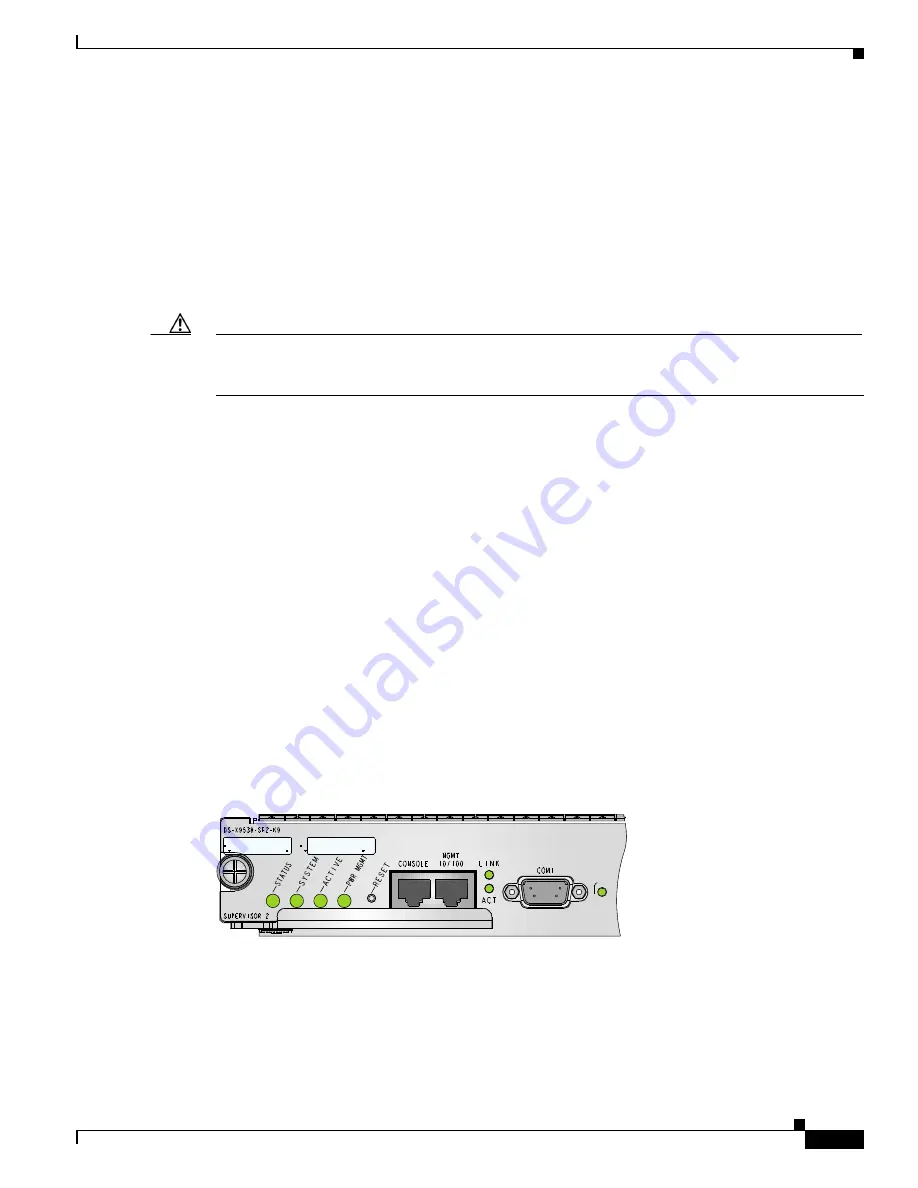
LEDs on the Supervisor-2 Module
The front panel on the supervisor module has the following LEDs:
•
Status LED
•
System LED
•
Active LED
•
Power Management LED
•
MGMT 10/100/1000 Ethernet port LEDs (at right of the port):
–
Link LED (on top)
–
Activity LED (on bottom)
•
CompactFlash LED for external CompactFlash card
The front panel on the Supervisor-2 module also includes a reset button (see
Figure 1-13
).
The LEDs on the Supervisor-2 module indicate the status of the Supervisor-2 module, power supplies,
and fan module.
Table 1-4
provides more information about these LEDs.
Figure 1-13
Supervisor-2 Module LEDs
144808


