INSTALLATION AND SETUP
2-42
Roadie 25K User’s Manual
2.
COARSE FOCUS:
Do a quick preliminary focus and (if available) zoom adjustment
with the primary lens only (see 3.14, Working with the Lenses). Do not worry
about consistency across the image at this point, just center focus.
3.
CENTER THE IMAGE IN THE LENS:
Holding a piece of paper at the lens surface,
adjust offsets as necessary until the image on the paper is centered within the lens
perimeter. A full white field works best for this.
4.
RE-CHECK SIDE-TO-SIDE LEVELING:
With a good test pattern on screen,
double-check projector leveling (see
2.3, Projector Position & Leveling)
so that the top edge of the image is
parallel to the top edge of the screen.
See right.
NOTES:1) Projector must
be installed and powered
up in its final location.
Install the anamorphic
lens if it will be used at
the site. 2) You will need
a 3/16” allen wrench. 3)
Boresight may need slight
adjustment after installing
a new lens.
To ensure proper offset
for your site and
consistently good focus in
all areas of the screen, a
primary lens must be
installed and its lens
mount precisely adjusted
in relation to internal
optics as described below.
If desired, an anamorphic lens can then be added to widen images for “scope”
displays. Once adjusted, boresight should remain stable until the lens is replaced.
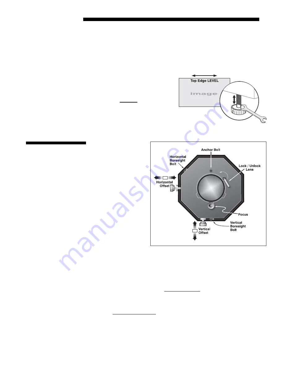
Refer to lens mount components illustrated in Figure 2.44 for these adjustments.
NOTE: Project an image using the primary lens only. The optional anamorphic lens,
if present, can be mounted but swung aside.
Prior to boresight adjustment, offset the image as required so that the image is square
on screen but offset is minimal. For best results, try to minimize offsets by “aiming”
the projector lens at the center of the image. Refer back to 2.3, Projector Position
and Mounting for offset ranges and method of adjustment.
Figure 2.43. Level the TOP Edge
2.12 Boresight
Adjustment
Figure 2.44. Adjusting the Lens Mount
Adjust Offset
'
Содержание Roadie 25K
Страница 6: ......
Страница 15: ...INSTALLATION AND SETUP Roadie 25K User s Manual 2 9 Figure 2 10 Switching Between Flat Scope Displays ...
Страница 56: ......
Страница 153: ...SPECIFICATIONS Roadie 25K User s Manual 6 7 ...
Страница 164: ......
Страница 165: ...Appendix B Remote Keypad Roadie 25K User s Manual B 1 Figure B 1 Standard Remote Keypad ...
Страница 166: ......
Страница 168: ...SERIAL COMMUNICATION CABLES C 2 Roadie 25K User s Manual ...
Страница 169: ...SERIAL COMMUNICATION CABLES Roadie 25K User s Manual C 3 ...
Страница 170: ......
Страница 186: ......


![NEC MT800[1].PART1 User Manual preview](http://thumbs.mh-extra.com/thumbs/nec/mt800-1-part1/mt800-1-part1_user-manual_250403-1.webp)


