background image

Access Navigator - Release 1.8

August 2003

6-37

 Electrical 

Installation

Verify Wiring

7. Orient the connector as shown in Figure 6-23 and loosen the right two set screws.

8. Insert the Battery Return and –48V VDC Battery wires into the appropriate square holes (see Figure 

6-23), one at a time, tightening the set screws as you go. 

9. Ensure that no bare wires are exposed. 

Verify Wiring

WARNING!   

I

NCORRECT


VOLTAGE


POLARITY


CAN


DAMAGE

 A

CCESS

 N

AVIGATOR

.

1. Use voltmeter to verify wiring of both power connectors (Figure 6-24) before plugging into Access 

Navigator.

2. Apply power to connector. (Replace fuse or turn on circuit breaker.)

3. Touch voltmeter probes to screw clamps below pins 2 and 3 of connector plug.

4. Verify that voltage is between –42V and –58V DC.

5. Verify that voltage is correct polarity.

6. Turn off power to connectors.

Connect Power Plugs to Access Navigator

1. Plug connectors into Access Navigator power input connectors (see Figure 6-24).

2. Plug one power plug into the rear panel connector market –48V A.

3. Plug other power plug into the rear panel connector market –48V B.

4. Inspect connectors to ensure that no bare copper wire is exposed.

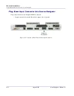
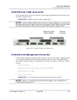
Figure 6-24. Location of Rear Panel Power Input Connectors

–48V Input ‘B’

Power Connector

–48V Input ‘A’

Power Connector

Содержание Access Navigator

Страница 1: ...Access Navigator USER MANUAL Part Number 770 0079 AP Product Release 1 8 August 2003 ...

Страница 2: ...ium electronic mechanical magnetic optical chemical manual or otherwise any part of this manual or software supplied with the Access Navigator for any purpose other than the purchaser s personal use without the express written permission of Carrier Access Corporation Access Navigator Access Bank Adit and the Carrier Access logo are registered trademarks of Carrier Access Corporation Valet and Netw...

Страница 3: ...PREFACE Preface In this Preface n Compliance iv n Notices iv n Electrostatic Discharge ESD Precautions v n Carrier Access Software License Agreement vi n Warranty ix ...

Страница 4: ...gs that must be followed to ensure safe operation of the equipment DANGER A DANGER NOTICE INDICATES THE PRESENCE OF A HAZARD THAT CAN OR WILL CAUSE DEATH OR SEVERE PERSONAL INJURY IF THE HAZARD IS NOT AVOIDED CAUTION A CAUTION NOTICE INDICATES THE POSSIBILITY OF INTERRUPTING NETWORK SERVICE IF THE HAZARD IS NOT AVOIDED WARNING A WARNING NOTICE INDICATES THE POSSIBILITY OF EQUIPMENT DAMAGE IF THE H...

Страница 5: ... of the system unit before handling components If a wrist strap is not available maintain contact with the system unit throughout any procedure requiring ESD protection 3 For more information see Static Sensitive Equipment Handling Procedures on page 3 WARNING INTEGRATED CIRCUITS ICS ARE EXTREMELY SUSCEPTIBLE TO ELECTRO STATIC DISCHARGE UNLESS YOU ARE A QUALIFIED SERVICE TECHNICIAN WHO USES TOOLS ...

Страница 6: ... was purchased LICENSEE may not transfer the Software from one unit to another even though the Software is used on only one unit at a time LICENSEE may not provide copies of the Software to any third party LICENSEE may make one copy of the Software solely for backup purposes LICENSEE may not modify the Software LICENSEE agrees that it will not attempt to alter disassemble decrypt or reverse engine...

Страница 7: ...e commercially reasonable efforts to correct any reproducible error in the Software reported to LICENSOR by LICENSEE in writing during the Software Warranty Period or to replace the defective Software If LICENSOR determines that it is unable to correct the error or replace the Software LICENSOR will refund to LICENSEE all license fees paid for the Software in which case this License and LICENSEE s...

Страница 8: ...OUNT EQUAL TO THE SOFTWARE LICENSE OR PURCHASE FEE PAID PRIOR TO THE TIME WHEN SUCH CAUSE OF ACTION ARISES REDUCED BY TWENTY PERCENT 20 FOR EACH SUBSEQUENT YEAR WHICH SHALL HAVE EXPIRED PRIOR TO THAT TIME Jurisdiction and Venue This License shall be construed and interpreted according to the laws of the state of Colorado Any action or proceeding arising from or relating to these License Terms shal...

Страница 9: ...ribed in Carrier Access Corporation s documentation or b the negligent or other improper use of the PRODUCT or c handling or transportation after title of the PRODUCT passes to BUYER Other manufacturer s equipment purchased by Carrier Access Corporation and resold to BUYER will be limited to that manufacture s warranty Carrier Access Corporation assumes no warranty liability for other manufacturer...

Страница 10: ...wing information l Carrier Access serial number s from the system chassis or circuit card s l Name of distributor or dealer from which you purchased the product l Description of defect Ensure that returned items are packaged properly l Follow Electrostatic Discharge ESD Precautions on page v l Enclose circuit cards in anti static wrappers l Cushion items to prevent damage during shipment l If repl...

Страница 11: ...itation of Remedies ix Warranty Product Returns x Table of Contents 1 Introduction Overview 1 2 Features and Benefits 1 3 Access Navigator Configurations 1 3 System Architecture 1 4 Carrier Access Support Products 1 5 Access Banks 1 5 Adit 600 1 5 Management 1 6 Command Line Interface 1 6 SNMP 1 7 Valet and NetworkValet EMS Software 1 8 2 Access Navigator DCS Service Manager Overview 2 2 System Ar...

Страница 12: ...ellcore Requirements 2 11 UL Requirements 2 11 CSA Requirements 2 12 Ordering Information 2 12 3 Access Navigator GR 303 Data Host Overview 3 2 System Architecture 3 3 Features and Benefits 3 4 GR 303 Services 3 4 DCS Services 3 6 Management Architecture 3 7 IP DS0 Management 3 7 FDL Management 3 8 Configuration 3 9 Applications 3 10 Interfaces 3 10 Specifications 3 11 GR 303 Operation 3 11 Crossc...

Страница 13: ...Phone Services 4 6 DCS Services 4 7 Management Architecture 4 8 IP DS0 Management 4 8 FDL Management 4 9 Configuration 4 10 Applications 4 11 Interfaces 4 11 Specifications 4 12 GR 303 Operation 4 12 Crossconnects 4 12 DS1 Interface 4 12 System Clocking 4 12 GR 303 Signaling 4 13 DCS Signaling 4 13 Management Interfaces 4 13 Protocols 4 13 Alarms 4 13 Compliance 4 14 Standards 4 14 Power 4 14 Envi...

Страница 14: ...Crossbars 5 11 Installation Summary 5 11 Precautions 5 11 Tools and Materials 5 11 Install Crossbars 5 12 Attach Mounting Brackets to Access Navigator 5 12 Attach Access Navigator to Crossbars 5 12 Vertical Wall Mount 5 15 Installation Summary 5 15 Precautions 5 15 Tools and Materials 5 16 Ensure Adequate Clearance 5 16 Prepare Plywood 5 16 Attach Mounting Brackets to Access Navigator 5 16 Attach ...

Страница 15: ...ble Optional 6 22 Connect Ethernet Cable to Access Navigator 6 24 Connect Ethernet Cable to Ethernet Hub 6 24 External Timing Source BITS Connection 6 25 Installation Summary 6 25 Tools and Materials 6 25 Make BITS Cable Optional 6 26 Connect BITS Cable 6 26 Alarm Output Connections 6 27 Installation Summary 6 27 Precautions 6 27 Tools and Materials 6 27 Wire Alarm Output Connector 6 28 Plug Outpu...

Страница 16: ...nput Connections 6 47 Exit Management Session 6 48 Install Redundant Controller Card 6 49 Installation Summary 6 49 Precautions 6 49 Tools and Materials 6 50 Verify Software Compatibility 6 50 Remove Front Cover 6 51 Install Controller Card 6 52 Verify Operation 6 53 Install Additional Quad T1 Framer Cards 6 55 Installation Summary 6 55 Precautions 6 55 Tools and Materials 6 55 Remove Front Cover ...

Страница 17: ... 7 9 Perform Management Operations 7 10 Exit Telnet Management Session When Finished 7 10 NetworkValet EMS and Valet Management 7 11 8 Provision Access Navigator Basic Provisioning Overview 8 2 Basic Provisioning Quick Guide 8 2 Obtain Provisioning Information 8 3 Verify System Equipment Configuration 8 4 Set System ID or CLLI Code 8 5 Set Date 8 6 Set Time 8 6 Set Ethernet Properties 8 7 Set User...

Страница 18: ...ch Type 10 14 Set System Clock Source 10 14 Provision Switch DS1s to Interface Group 10 15 Assign Primary and Secondary EOC 10 18 Assign Primary and Secondary TMC 10 19 Test DS1 Circuits 10 20 Provision Drop DS1 Circuits to Subscriber 10 21 Provision ISDN BRI 4 1 TDM Service to Subscribers 10 25 Provision DS0s to Subscribers 10 30 Assign Call Reference Values CRVs 10 32 Turn Up Service 10 34 Test ...

Страница 19: ...n 12 3 Remote Adit 600 FDL Provisioning Quick Guide 12 4 Obtain Provisioning Information 12 6 Verify Equipment Configuration 12 6 Provision Drop DS1s to Remote Adit 600 12 10 Provision Drop DS0s 12 13 Provision DS0 Crossconnects if required 12 15 Provision Remote Adit 600 12 17 Test DS1 and DS0 Circuits 12 17 13 Provision Remote Adit 600 via IP DS0 Remote IP DS0 Provisioning Overview 13 2 IP DS0 M...

Страница 20: ...nostics Troubleshooting Alarms and Logs 15 2 Operations Interface 15 2 Alarms 15 2 Alarm Reporting 15 3 Alarm Testing 15 3 Alarm and Status Indicators 15 3 Facility Alarm System 15 4 Alarm Cutoff ACO 15 4 Alarm Signaling Red Yellow RAI Blue AIS 15 4 DS1 Failures 15 5 Event Log 15 5 Configuration Change Log 15 6 BERT Log 15 7 TMC Log 15 7 Alarm and Status Indicators 15 8 Indicator Locations 15 8 In...

Страница 21: ... 15 36 Read Remote Loopback 15 36 Send Remote Loopdown 15 36 Send Remote RS232 Line Loopup 15 37 Send Remote RS232 TSI Equipment Loopup 15 37 Send Remote RS232 TSI Network Loopup 15 38 Send Remote SDSL Payload Loopup 15 38 Send Remote T1 Payload Loopup 15 39 Send Remote T1 TSI Loopup 15 39 Send Remote T1 Drop Line Loopup 15 40 Send Remote T1 Drop Payload Loopup 15 40 Send Remote T1 Drop Payload Lo...

Страница 22: ...view 17 2 Download Procedures 17 2 Update Software via TFTP Two Controllers 17 3 Procedure Summary 17 3 Overview 17 3 Precautions 17 4 Information and Materials Required 17 5 Install Optional TFTP Server Software 17 5 Verify Equipment Status 17 6 Verify IP Connectivity 17 7 Upload Configuration 17 7 Download Software 17 8 Download Configuration 17 10 Update Software via Xmodem Two Controllers 17 1...

Страница 23: ... Basic Commands 18 10 Context Sensitive Help 18 11 Printing the Help File 18 13 Users and Passwords 18 14 Administration 18 14 Access Levels 18 14 Managing Users 18 15 Logging In and Out 18 18 Startup Message 18 18 Login with No User Name Required 18 18 Login with User Name Required 18 19 Login with No Password Required 18 19 Login with Password Required 18 19 Logout Exit 18 20 Autoexit CLI Sessio...

Страница 24: ... Read Remote Loopback 18 51 Read Remote RS232 18 51 Read Remote Performance 18 52 Read Remote T1 18 54 Read Remote T1drop 18 55 Read Remote V35 18 56 Reset All 18 57 Reset DS1 Framer 18 57 Reset Remote 18 58 Reset Standby 18 58 Restore Defaults 18 59 Send DS1 CSU Loopup 18 62 Send DS1 Line Loopup 18 63 Send DS1 Line pattern 18 65 Send DS1 Line pattern Test 18 67 Send DS1 Network Loopup 18 70 Send ...

Страница 25: ... CRV 18 96 Set DS0 ISDN BRI CRV 18 100 Set DS0 P Phone 18 101 Set DS0 Service 18 102 Set DS0 Signal 18 103 Set DS0 Type 18 104 Set DS1 Clock 18 105 Set DS1 FDL 18 105 Set DS1 Framing 18 107 Set DS1 ID 18 108 Set DS1 LBO 18 108 Set DS1 Line Loopup 18 108 Set DS1 Linecode 18 109 Set DS1 Loopdetect 18 110 Set DS1 Payload Loopup 18 111 Set DS1 Remote Device Mgmt 18 112 Set DS1 Service 18 113 Set DS1 T...

Страница 26: ... GetCom 18 127 Set SNMP Location 18 128 Set SNMP Name 18 128 Set SNMP NMS Address 18 129 Set SNMP SetCom 18 129 Set SNMP TrapCom 18 130 Set Switch Type 18 130 Set Time 18 131 Set TMC 18 131 Set User Level 18 132 Set User Password 18 133 Show Autoexit 18 134 Show Clock 18 134 Show Connect 18 134 Show CRV 18 136 Show Date 18 138 Show DS0 18 138 Show DS1 18 139 Show DS1 All 18 142 Show EOC 18 144 Sho...

Страница 27: ...2 Managed Object Class Support A 4 Analog Line Termination Objects A 5 Alarm Count List Objects A 5 DS0 Channel Termination Objects A 6 DS1 Framed Path Termination Objects A 6 DS1 Line Termination Objects A 7 EBS Line Termination Objects A 7 ISDN Line Termination Objects A 8 ISDN Framed Path Termination Objects A 8 Quarter DS0 Channel Termination A 10 Crossconnection A 10 Equipment Objects A 11 ID...

Страница 28: ...isioning Requirements B 3 Adit 600 TDM Remote Provisioning Requirements B 3 Remote Provisioning Capabilities B 4 Access Bank II Capabilities B 4 C SNMP Interface Overview C 2 Carrier Access Enterprise MIB C 3 SNMP Basics C 4 MIB Structure C 4 MIB Tables C 5 Managing Networks C 6 SNMP Protocols C 7 SNMP Requirements C 8 SNMP Trap Reports C 9 Glossary Abbreviations Acronyms Glossary 1 Definitions Gl...

Страница 29: ...CHAPTER Introduction In this Chapter n Overview 1 2 n Features and Benefits 1 3 n Access Navigator Configurations 1 3 n System Architecture 1 4 n Carrier Access Support Products 1 5 n Management 1 6 ...

Страница 30: ...ts easily into small collocation spaces and phone closets Software configuration options include l DCS Service Manager l GR 303 with Data Host l GR 303 Host with P Phone The Access Navigator is a complete solution for managing 4 to 32 T1 access connections In conjunction with Carrier Access remotely managed Adit 600 and Access Bank families of T1 voice and data access products the Access Navigator...

Страница 31: ...r management via Ethernet IP Telnet SNMP Valet and NetworkValet EMS software l Remote management of CA s Adit 600 and Access Bank II terminals via T1 Facility Data Link l Remote management of CA s Adit 600 terminals using IP commands via T1 DS0 channel Access Navigator Configurations With up to 32 DS1 interfaces the Access Navigator has the capacity and flexibility to deploy a variety of voice and...

Страница 32: ...vices Drop DS1s 24 Lines PBX Key System Modem Fax Stations Access Bank I Voice ACCESS BANK I Tip R ing 48Vdc Retu rn Grou nd T1 Framing Output Monito r Input Monitor Alarm Cut Off T1 Test Network Loopba ck Normal Normal Normal Self Test Normal Remote Status Key System Fax V 35 T1 or DSL Router Ethernet PBX Stations Access Bank II Voice and Data Voice Lines A CCESS BANK II Tip Rin g 48Vd c Retu rn ...

Страница 33: ... Bank II up to 24 voice channels plus T1 and V 35 data interfaces l Access Bank II SNMP up to 24 voice channels plus T1 and V 35 data and Ethernet SNMP l Access Bank II SDSL up to 24 voice channels plus SDSL and V 35 data interfaces Adit 600 Adit 600 family of Customer Service Terminals see Figure 1 2 includes l Adit 600 TDM 6 service card slots support up to 18 T1s per unit up to 48 voice channel...

Страница 34: ...command line interface is a simple user interface that controls configuration and maintenance operations There are two ways to use the command line interface l A VT 100 terminal or a PC running terminal emulation software such as Hyper Terminal connected to the 9 pin DB9 RS 232 port The port runs at 9600 baud 8 data bits 1 stop bit no parity and no flow control l A Telnet connection using the 10Ba...

Страница 35: ... Navigator features not included in the standard MIB RFC 1213 It also enables remote management of CA products connected via the T1 facility data link FDL to the Access Navigator Figure 1 1 The CA Enterprise MIB supports l Access Navigator system configuration settings including SNMP l Access Navigator interface management l DS1 management features not supported by the standard MIB l DS0 managemen...

Страница 36: ...er Access products including the Access Navigator and Adit 600 Valet and NetworkValet are cross platform Java applications that run on either Microsoft Windows and Solaris based computer systems Java Runtime Engine JRE software for Windows or Solaris is included with the Valet and NetworkValet installation programs Valet and NetworkValet send commands over the carrier s IP network to communicate w...

Страница 37: ...vice Manager In this Chapter n Overview 2 2 n System Architecture 2 3 n Features and Benefits 2 4 n Configuration 2 6 n Applications 2 7 n Interfaces 2 7 n Specifications 2 7 n Compliance Requirements 2 10 n Ordering Information 2 12 ...

Страница 38: ...provides the functionality of a miniature 1 0 digital crossconnect switch DCS Providing up to 32 DS1 ports 768 DS0s in one small package the Access Navigator fits easily into small collocation spaces and phone closets The Access Navigator is a complete solution for managing 4 to 32 T1 access connections In conjunction with Carrier Access remotely managed Adit 600 and Access Bank families of T1 voi...

Страница 39: ...ns Access Bank I Voice ACCESS BAN K I Tip Ring 4 8Vdc Return Ground T1 Framing Outp ut Moni tor Input Monitor Alarm Cut O ff T1 Test Netw ork Loopback Norm al Normal Normal Self Test Normal Rem ote Statu s Key System Fax V 35 T1 or DSL Router Ethernet PBX Stations Access Bank II Voice and Data Voice Lines ACCESS BAN K II Tip Ring 48Vdc Return Gro und T1 Span 1 T1 Test 2 T1 Test 1 T1 Span 2 V 35 DC...

Страница 40: ...ice and data services from multiple customers and applications are combined by the Access Navigator to save recurring backhaul transmission costs and capital costs on switch or router ports Facilities With both NEBS and customer premise certifications the Access Navigator can be located in carrier racks or on customer walls Space power and installation labor are dramatically reduced in comparison ...

Страница 41: ...h FDL On Net Location Customer Wiring Closet Local Management CLI RS 232 CLI Telnet SNMP Data Switch TCP IP Network Customer Premises Key System Fax V 35 T1 or DSL Router Ethernet PBX Stations Voice Lines ACCESS BANK II Tip Ring 48Vdc Return Ground T1 Span 1 T1 Test2 T1 Test 1 T1 Span 2 V 35 DCE V 35 Status RS232 Data Adit 600 Key System Fax Router Ethernet PBX Stations Modem FXS FXO 10 100BaseT A...

Страница 42: ... Figure 2 4 Access Navigator Hardware Configuration Technology Advantages Low Cost Small Size Low Power Surge Protection Test Integration Fault Isolation No Fans Four T1 circuits per card Up to 8 cards 32 T1s 1 0 cross connections Groom and fill T1s Fuseless high voltage protection Built in T1 CSU Hot swappable Power and control circuit redundancy Ethernet Telnet and SNMP remote management Built i...

Страница 43: ...r receive input and one for transmit output l RJ45C Interface Timing input connector for external clock source such as BITS l RS 232 Interface DB9 DE9 female connector for CLI management by craft terminal or computer with terminal emulation software l Ethernet Interface 10Base T connector for SNMP and Telnet CLI management Specifications DCS Operation l Up to 32 T1s per system l DCS 1 0 interface ...

Страница 44: ...rt robbed bit signaling l E M robbed bit signaling Management Interfaces l Command line interface CLI for provisioning and maintenance l RS 232 interface for local CLI l Ethernet Telnet support for remote CLI l Ethernet SNMP uses Telcordia standard MIB for DS1 interfaces RFC 1406 l TFTP and Xmodem support for flash memory software upgrades Protocols l Command Line Interface CLI l Simple Network Ma...

Страница 45: ... to 60 VDC 1 5A l Dual feed DC power input terminals l Power dissipation 65 watts 225 Btu hr fully equipped l Solid state fuse less over voltage and over current protection Environmental l Operating temperature 5 C to 45 C 23 F to 113 F up to 55 C short term NEBS l Solid state over temperature protection l Relative humidity 0 to 95 non condensing l No fans Passive thermal management Physical l Dim...

Страница 46: ...lded to maintain FCC Part 15 compliance l Both DSX 1 cables l RS 232 cable Part 68 This equipment complies with Part 68 of the Federal Communications Commission rules The silkscreen on the top cover of this equipment includes the FCC registration number You must supply the following information to the telephone company if they request it l FCC Registration Number 2Z6USA 33482 DD N l Service Center...

Страница 47: ...in compliance with the GR 1089 CORE requirements to prevent EMI EMC radio frequency interference with other equipment the DSX 1 and RS 232 cables must be shielded and have ferrite bead RFI suppressors UL Requirements This equipment conforms with Underwriters Laboratory standard UL 1950 supersedes UL 1459 To maintain this compliance all access covers must be replaced after servicing the equipment t...

Страница 48: ... 740 0018 Quad T1 Framer Card Access Navigator Quad T1 Framer card terminates 4 T1 interfaces from switch customer site or data network 005 0025 DSX 1 Cable 64 pin DSX 1 cable 10 feet long male male Two cables must be ordered per Access Navigator one TX one RX May be used for DS1 and DSX 1 transmission levels 005 0030 DSX 1 Cable 64 pin DSX 1 cable 25 feet long see 005 0025 710 0153 19 23 Universa...

Страница 49: ...w 3 2 n System Architecture 3 3 n Features and Benefits 3 4 n GR 303 Services 3 4 n DCS Services 3 6 n Management Architecture 3 7 n Configuration 3 9 n Applications 3 10 n Interfaces 3 10 n Specifications 3 11 n Compliance Requirements 3 14 n Ordering Information 3 16 ...

Страница 50: ...ustomer T1 access lines Using the Telcordia standard GR 303 switching protocol up to 672 customer telephone channels can be assigned on a call by call basis to Class 5 local digital switch T1 connections In addition to the concentration and management of CLASS voice services the Access Navigator grooms and optionally concentrates fractional T1 data connections from customer locations Figure 3 1 Ac...

Страница 51: ...g 48Vd c Return Groun d T1 Fr aming O utput Monitor In put Monitor A larm C ut Off T1 Test Network L oopback N ormal Normal Normal Self Test Normal Remote Status Key System Fax V 35 T1 or DSL Router Ethernet PBX Stations Access Bank II Voice and Data Voice Lines A CCESS BANK II Ti p Rin g 48Vdc Return Groun d T1 Span 1 T 1 Test2 T1 Test 1 T1 Span 2 V 35 DCE V 35 Status RS232 Data DDS ISDN BRI T1 D...

Страница 52: ...S switches l Digital crossconnect system l T1 CSUs and demarcation testing l Ethernet Telnet and SNMP management l Optional Controller redundancy l Modular Quad T1 expansion l NEBS Certified GR 303 Services The Access Navigator GR 303 Data Host provides T1 local voice and data services to multiple customers see Figure 3 3 Using GR 303 switching protocol for call concentration the Access Navigator ...

Страница 53: ...erminal IDT Remote Digital Terminal RDT Drop DS1s 24 Lines PBX Key System Modem Fax Stations Access Bank I Voice ACCESS BANK I Tip Ring 48Vdc Return Gr ound T1 Frami ng Output Monitor Input Moni tor Alarm Cut O ff T1 Tes t Network Loop back Normal Norm al Norm al Self Test Norm al Remote Status Key System Fax V 35 T1 or DSL Router Ethernet PBX Stations Access Bank II Voice and Data Voice Lines ACC...

Страница 54: ...agement RS 232 Drop DS1s Access Navigator Ethernet Telnet SNMP Data Network Voice Switch Groom T1s Internet Data Private and Special Services DCS Voice and Data Voice Public Network 24 Lines PBX Key System Modem Fax Stations Access Bank I Voice ACCESS BAN K I Tip Ring 4 8Vdc Return Ground T1 Framing Outp ut Moni tor Input Monitor Alarm Cut O ff T1 Test Netw ork Loopback Norm al Normal Normal Self ...

Страница 55: ...oom DS1 The Access Navigator then cross connects the groom DS0s to a dedicated drop DS0 going to each remote Adit 600 Customers wishing to conserve IP addresses can use an Ethernet hub or router providing port addresses translation NAT to isolate the IP DS0 management network Figure 3 5 Access Navigator IP DS0 Management Architecture DS1 ST ATUS ACCESS NAVIGATOR CARR I ER ACCESS COR PORA TION 1 2 ...

Страница 56: ...Access Navigator Network Operations Center Access Navigator Element Manager Voice Switch FDL On Net Location Customer Wiring Closet Local Management CLI RS 232 CLI Telnet SNMP Data Switch TCP IP Network Customer Premises Key System Fax V 35 T1 or DSL Router Ethernet PBX Stations Voice Lines ACCESS BANK II Tip Ring 48Vdc Return Ground T1 Span 1 T1 Test2 T1 Test 1 T1 Span 2 V 35 DCE V 35 Status RS23...

Страница 57: ...iguration Operating system is stored in upgradeable flash memory Configuration and provisioning data are stored in nonvolatile RAM protected from power interruptions Figure 3 7 Access Navigator Hardware Configuration Technology Advantages Low Cost Small Size Low Power Surge Protection Test Integratino Fault Isolation No Fans Four T1 circuits per card Up to 8 cards 32 T1s 1 0 cross connections Groo...

Страница 58: ...provisioning protection and service management l Host Control of Access Bank II Flow through remote management and bandwidth grooming of Access Bank IIs Interfaces l DS1 Interface Two Champ 64 pin connectors with 32 DS1 circuits one for receive input and one for transmit output l RJ45C Interface Timing input connector for external clock source such as BITS l RS 232 Interface DB9 DE9 connector for ...

Страница 59: ...lues CRVs l Redundancy 1 1 controller power conversion Crossconnects l DCS 1 0 interface supports crossconnects at DS0 level l Crossconnects up to 24 contiguous DS0s between T1s with one command DS1 Interface l Four T1s per line card hot swappable l Line rate 1 544 Mb s 32ppm l Line code B8ZS or AMI l Framing D4 SF or ESF l DS1 receive sensitivity 28dB to 1 5dB l Line build outs DSX 1 0 to 660 ft ...

Страница 60: ...isioning and maintenance l RS 232 interface for local CLI l Ethernet Telnet support for remote CLI l Ethernet SNMP uses Telcordia standard MIB for DS1 interfaces RFC 1406 l TFTP and Xmodem support for flash memory software upgrades Protocols l Command Line Interface CLI l Simple Network Management Protocol SNMP l Telcordia GR 303 l Telnet l TFTP and Xmodem support for flash memory software upgrade...

Страница 61: ...to 60 VDC 1 5A l Dual feed DC power input terminals l Power dissipation 65 watts 225 Btu hr fully equipped l Solid state fuse less over voltage and over current protection Environmental l Operating temperature 5 C to 45 C 23 F to 113 F up to 55 C short term NEBS l Solid state over temperature protection l Relative humidity 0 to 95 non condensing l No fans Passive thermal management Physical l Dime...

Страница 62: ...ded to maintain FCC Part 15 compliance l Both DSX 1 cables l RS 232 cable Part 68 This equipment complies with Part 68 of the Federal Communications Commission rules The silkscreen on the top cover of this equipment includes the FCC registration number You must supply the following information to the telephone company if they request it l FCC Registration Number 2Z6USA 33482 DD N l Service Center ...

Страница 63: ...n compliance with the GR 1089 CORE requirements to prevent EMI EMC radio frequency interference with other equipment the DSX 1 and RS 232 cables must be shielded and have ferrite bead RFI suppressors UL Requirements This equipment conforms with Underwriters Laboratory standard UL 1950 supersedes UL 1459 To maintain this compliance all access covers must be replaced after servicing the equipment to...

Страница 64: ...18 Quad T1 Framer Card Access Navigator Quad T1 Framer card terminates 4 T1 interfaces from switch customer site or data network 005 0025 DSX 1 Cable 64 pin DSX 1 cable 10 feet long male male Two cables must be ordered per Access Navigator one TX one RX May be used for DS1 and DSX 1 transmission levels 005 0030 DSX 1 Cable 64 pin DSX 1 cable 25 feet long see 005 0025 710 0153 19 23 Universal Mount...

Страница 65: ...System Architecture 4 3 n Features and Benefits 4 4 n GR 303 Services 4 4 n P Phone Services 4 6 n DCS Services 4 7 n Management Architecture 4 8 n Configuration 4 10 n Applications 4 11 n Interfaces 4 11 n Specifications 4 12 n Compliance Requirements 4 15 n Ordering Information 4 17 ...

Страница 66: ...ustomer telephone channels can be assigned on a call by call basis to Class 5 local digital switch T1 connections When connected to a Nortel DMS switch providing Nortel Proprietary Phone P Phone Centrex service the Access Navigator can support up to 384 P Phone channels from up to 14 remote Adit 600s In addition to the concentration and management of CLASS voice services the Access Navigator groom...

Страница 67: ... 48Vdc Retu rn Grou nd T1 Framing Output Monito r Input Monitor Alarm Cut Off T1 Test Network Loopba ck Normal Normal Normal Self Test Normal Remote Status Key System Fax V 35 T1 or DSL Router Ethernet PBX Stations Access Bank II Voice and Data Voice Lines A CCESS BANK II Tip Rin g 48Vd c Retu rn Grou nd T 1 Sp an 1 T 1 Test2 T1 Test 1 T 1 Sp an 2 V 35 DCE V 35 Status RS232 Data DDS ISDN BRI T1 Dr...

Страница 68: ...tem l T1 CSUs and demarcation testing l Ethernet Telnet and SNMP management l Optional Controller redundancy l Modular Quad T1 expansion l NEBS Certified GR 303 Services The Access Navigator GR 303 Host with P Phone provides T1 local voice P Phone and data services to multiple customers Figure 4 3 Using GR 303 switching protocol for call concentration the Access Navigator reduces recurring backhau...

Страница 69: ...SS BANK I Tip Ring 48Vdc Return Gr ound T1 Frami ng Output Monitor Input Moni tor Alarm Cut O ff T1 Tes t Network Loop back Normal Norm al Norm al Self Test Norm al Remote Status Key System Fax V 35 T1 or DSL Router Ethernet PBX Stations Access Bank II Voice and Data Voice Lines ACCESS BANK II Tip Ring 48Vdc Return Gr ound T1 Span 1 T1 Tes t2 T1 Test 1 T1 Span 2 V 35 DCE V 35 Statu s RS23 2 Data A...

Страница 70: ... digital signals that are then transmitted over DS0s on the Access Navigator s drop DS1 Command and signaling information for all P Phones is carried by message packets sent over the IP DS0 management channel between the Access Navigator and remote Adit 600 then over the GR 303 EOC channel between the Access Navigator and the Nortel DMS switch The Access Navigator can support up to 384 P Phone cha...

Страница 71: ... Management RS 232 Drop DS1s Access Navigator Ethernet Telnet SNMP Data Network Voice Switch Groom T1s Internet Data Private and Special Services DCS Voice and Data Voice Public Network 24 Lines PBX Key System Modem Fax Stations Access Bank I Voice ACCESS BAN K I Tip Ring 4 8Vdc Return Ground T1 Framing Outp ut Moni tor Input Monitor Alarm Cut O ff T1 Test Netw ork Loopback Norm al Normal Normal S...

Страница 72: ... IP port and the 24 DS0s on a groom DS1 The Access Navigator then cross connects the groom DS0s to a dedicated drop DS0 going to each remote Adit 600 Customers wishing to conserve IP addresses can use an Ethernet hub or router providing port addresses translation NAT to isolate the IP DS0 management network Figure 4 6 Access Navigator IP DS0 Management Architecture DS1 ST ATUS ACCESS NAVIGATOR CAR...

Страница 73: ...t Architecture T1 Access Bank II Access Navigator Network Operations Center Access Navigator Element Manager Voice Switch FDL On Net Location Customer Wiring Closet Local Management CLI RS 232 CLI Telnet SNMP Data Switch TCP IP Network Customer Premises Key System Fax V 35 T1 or DSL Router Ethernet PBX Stations Voice Lines ACCESS BANK II Tip Ring 48Vdc Return Ground T1 Span 1 T1 Test2 T1 Test 1 T1...

Страница 74: ...re configuration Operating system is stored in upgradeable flash memory Configuration and provisioning data are stored in nonvolatile RAM protected from power interruptions Figure 4 8 Access Navigator Hardware Configuration Technology Advantages Low Cost Small Size Low Power Surge Protection Test Integratino Fault Isolation No Fans Four T1 circuits per card Up to 8 cards 32 T1s 1 0 cross connectio...

Страница 75: ...olidation provisioning protection and service management l Host Control of Access Bank II Flow through remote management and bandwidth grooming of Access Bank IIs Interfaces l DS1 Interface Two Champ 64 pin connectors with 32 DS1 circuits one for receive input and one for transmit output l RJ45C Interface Timing input connector for external clock source such as BITS l RS 232 Interface DB9 DE9 conn...

Страница 76: ...mens switches l Configurable concentration ratios l Programmable call reference values CRVs l Redundancy 1 1 controller power conversion Crossconnects l DCS 1 0 interface supports crossconnects at DS0 level l Crossconnects up to 24 contiguous DS0s between T1s with one command DS1 Interface l Four T1s per line card hot swappable l Line rate 1 544 Mb s 32ppm l Line code B8ZS or AMI l Framing D4 SF o...

Страница 77: ...LI for provisioning and maintenance l RS 232 interface for local CLI l Ethernet Telnet support for remote CLI l Ethernet SNMP uses Telcordia standard MIB for DS1 interfaces RFC 1406 l TFTP and Xmodem support for flash memory software upgrades Protocols l Command Line Interface CLI l Simple Network Management Protocol SNMP l Telcordia GR 303 l Nortel NIS V202 1 Issue 01 P Phone l Telnet l TFTP and ...

Страница 78: ...1 403 and T1 107a Power l Input power 42 to 60 VDC 1 5A l Dual feed DC power input terminals l Power dissipation 65 watts 225 Btu hr fully equipped l Solid state fuse less over voltage and over current protection Environmental l Operating temperature 5 C to 45 C 23 F to 113 F up to 55 C short term NEBS l Solid state over temperature protection l Relative humidity 0 to 95 non condensing l No fans P...

Страница 79: ...hielded to maintain FCC Part 15 compliance l Both DSX 1 cables l RS 232 cable Part 68 This equipment complies with Part 68 of the Federal Communications Commission rules The silkscreen on the top cover of this equipment includes the FCC registration number You must supply the following information to the telephone company if they request it l FCC Registration Number 2Z6USA 33482 DD N l Service Cen...

Страница 80: ...ntain compliance with the GR 1089 CORE requirements to prevent EMI EMC radio frequency interference with other equipment the DSX 1 and RS 232 cables must be shielded and have ferrite bead RFI suppressors UL Requirements This equipment conforms with Underwriters Laboratory standard UL 1950 supersedes UL 1459 To maintain this compliance all access covers must be replaced after servicing the equipmen...

Страница 81: ...S software 740 0018 Quad T1 Framer Card Access Navigator Quad T1 Framer card terminates 4 T1 interfaces from switch customer site or data network 005 0025 DSX 1 Cable 64 pin DSX 1 cable 10 feet long male male Two cables must be ordered per Access Navigator one TX one RX May be used for DS1 and DSX 1 transmission levels 005 0030 DSX 1 Cable 64 pin DSX 1 cable 25 feet long see 005 0025 710 0153 19 2...

Страница 82: ...4 18 August 2003 Access Navigator Release 1 8 Access Navigator GR 303 Host with P Phone Ordering Information ...

Страница 83: ...ter n Compliance and Safety Requirements 5 2 n Tools and Materials 5 3 n Unpacking and Inspection 5 3 n Horizontal 19 Inch Rack Mount 5 4 n Horizontal 23 Inch Rack Mount 5 7 n Vertical Rack Mount Using Crossbars 5 11 n Vertical Wall Mount 5 15 ...

Страница 84: ...TE RF SUPPRESSOR BEADS AND SHIELDED ETHERNET AND BITS CLOCK CABLES TO PREVENT RADIO FREQUENCY INTERFERENCE WITH OTHER EQUIPMENT WARNING NEBS REQUIREMENT DO NOT CONNECT THIS EQUIPMENT DIRECTLY TO METALLIC TIP AND RING OUTSIDE PLANT CONDUCTORS THIS EQUIPMENT CAN ONLY BE USED FOR INTRA BUILDING INSIDE PLANT INSTALLATION IN A CENTRAL OFFICE OR CUSTOMER PREMISES WARNING THE ACCESS NAVIGATOR CONTAINS CI...

Страница 85: ... outside of Access Navigator shipping container Packing lists show only top level part numbers 2 Compare packing list with office records Report any discrepancies to the office 3 Open shipping containers Be careful not to damage contents WARNING DO NOT OPEN EQUIPMENT COVERS OR ANTI STATIC PLASTIC BAGS UNTIL READY FOR INSTALLATION ALWAYS FOLLOW THE STATIC SENSITIVE EQUIPMENT HANDLING PROCEDURES ON ...

Страница 86: ... AIR SPACE ABOVE AND BELOW CHASSIS FOR AIR CIRCULATION INSUFFICIENT SPACING MAY CAUSE SERVICE INTERRUPTIONS RESULTING FROM EQUIPMENT OVERHEATING AND SHUTTING DOWN Tools and Materials Obtain the following tools and materials Screwdrivers Phillips 2 and 3 Screwdrivers slotted Universal rack mounting bracket kit PN 710 0153 included with Access Navigator Rack mounting screws 4 ea as appropriate for e...

Страница 87: ... be attached 4 Attach mounting brackets to sides of Access Navigator using mounting screws removed in previous step see B in Figure 5 2 Attach Access Navigator to Equipment Rack CAUTION ACCESS NAVIGATOR REQUIRES AT LEAST 4 37 INCHES 2 5 RACK UNITS OF FREE AIR SPACE ABOVE AND BELOW CHASSIS FOR AIR CIRCULATION INSUFFICIENT SPACING MAY CAUSE SERVICE INTERRUPTIONS RESULTING FROM EQUIPMENT OVERHEATING ...

Страница 88: ...ack Figure 5 3 Spacing Requirements Mount bracket here for flush mount Mounting Bracket Mount bracket here for 5 inch forward offset Fasten brackets to Access Navigator with 6 32 x 3 8 undercut screws four per side Fasten brackets to equipment rack with appropriate mounting screws two per side Mounting Bracket B C A 4 37 inches minimum 7 00 inches minimum ...

Страница 89: ...TS OF FREE AIR SPACE ABOVE AND BELOW CHASSIS FOR AIR CIRCULATION INSUFFICIENT SPACING MAY CAUSE SERVICE INTERRUPTIONS RESULTING FROM EQUIPMENT OVERHEATING AND SHUTTING DOWN Tools and Materials Obtain the following tools and materials Phillips screw drivers 2 and 3 Universal rack mounting bracket kit PN 710 0153 included with Access Navigator Rack mounting screws 4 ea as appropriate for equipment r...

Страница 90: ... inch racks see Figure 5 4 Attach each mounting bracket to a bracket extender with two 12 24 5 8 inch screws 3 Position mounting brackets for required flush mount or 5 inch forward offset with respect to front rails of equipment rack see A in Figure 5 5 4 Remove four mounting screws 6 32 3 8 inch 82º undercut Phillips from each side of Access Navigator where brackets will be attached 5 Attach moun...

Страница 91: ... AND BELOW CHASSIS FOR AIR CIRCULATION INSUFFICIENT SPACING MAY CAUSE SERVICE INTERRUPTIONS RESULTING FROM EQUIPMENT OVERHEATING AND SHUTTING DOWN Figure 5 5 Installation in 23 inch Equipment Rack Mount brackets here for flush mount Mount brackets here for 5 inch forward offset Fasten brackets to Access Navigator with 6 32 x 3 8 undercut screws four per side A B C Fasten brackets to equipment rack...

Страница 92: ...esulting from equipment overheating and shutting down 2 Position Access Navigator in equipment rack slot refer to office records Ensure that there is at least 4 37 inches 2 5 rack units of free air space above and below chassis for cooling see Figure 5 6 on page 5 10 3 Secure mounting brackets to equipment rack using appropriate mounting screws see C in Figure 5 5 Brackets accommodate 1 75 and 2 0...

Страница 93: ...SULTING FROM EQUIPMENT OVERHEATING AND SHUTTING DOWN IF INSTALLING MORE THAN ONE ROW OF UNITS ENSURE THAT UNITS ARE MOUNTED DIRECTLY ABOVE OR BELOW UNITS IN OTHER ROWS TO MAINTAIN UNOBSTRUCTED VERTICAL AIR CIRCULATION Tools and Materials Obtain the following tools and materials Phillips screw drivers 2 and 3 Vertical Mount Crossbars 2 per kit PN 710 0003 for 19 inch racks or PN 710 0004 for 23 inc...

Страница 94: ...nt rails of equipment rack see B in Figure 5 8 3 Remove four mounting screws 6 32 3 8 inch 82º undercut Phillips from each side of Access Navigator where brackets will be attached 4 Attach mounting brackets to each side of Access Navigator using the mounting screws removed in previous step see C in Figure 5 8 Attach Access Navigator to Crossbars CAUTION ACCESS NAVIGATOR REQUIRES AT LEAST 0 75 INCH...

Страница 95: ...l Installation Attach Access Navigator to Crossbars Figure 5 7 Crossbar Installation Fasten Crossbars to equipment rack with appropriate mounting screws two per side B Position inside mounting holes 18 375 18 3 8 inches apart A Slotted hole Key hole 1 75 ...

Страница 96: ...nting Brackets Mount bracket here for 5 inch forward offset Fasten brackets to Access Navigator with 6 32 x 3 8 undercut screws four per side C A D Fasten brackets to crossbar with 12 24 x 5 8 inch machine screws two per side B 19 inch Equipment Rack 5 units per row maximum 23 inch Equipment Rack 6 units per row maximum 1 75 inch Bracket spacing 0 75 inch Minimum air space A B C D E A B C D E F 1 ...

Страница 97: ...ch Access Navigator to Plywood 5 17 Precautions CAUTION WALL MOUNTING IS APPROVED ONLY FOR CUSTOMER PREMISES CAUTION ACCESS NAVIGATOR REQUIRES FREE AIR SPACE ON TOP BOTTOM AND ENDS OF CHASSIS FOR AIR CIRCULATION INSUFFICIENT VENTILATION MAY CAUSE SERVICE INTERRUPTIONS RESULTING FROM EQUIPMENT OVERHEATING AND SHUTTING DOWN DO NOT ALLOW CABLES AND OTHER COMPONENTS TO OBSTRUCT AIR CIRCULATION THE ACC...

Страница 98: ...ckets 2 Mark mounting hole locations on plywood to ensure that brackets will mount squarely against plywood see Figure 5 12 on page 5 20 Attach Mounting Brackets to Access Navigator NOTE Universal mounting kit includes hardware that is not required for wall mount installation 1 Open bags containing the universal mounting kits and select the following items see A in Figure 5 13 on page 5 21 Mountin...

Страница 99: ...on page 5 20 2 Secure mounting brackets to plywood using eight 8 3 4 inch panhead screws see D in Figure 5 13 on page 5 21 WARNING IF ACCESS NAVIGATOR IS MOUNTED ON PLYWOOD DO NOT USE A HAMMER TO ATTACH PLYWOOD TO WALL BECAUSE THE IMPACT SHOCK MAY DAMAGE THE ACCESS NAVIGATOR AND OTHER COMPONENTS MOUNTED ON THE PLYWOOD A POWER DRILL AND SCREWDRIVER IS RECOMMENDED TO AVOID DAMAGE 3 Attach plywood to...

Страница 100: ...ce Requirements Control Panel and Circuit Board Access Connector Panel Access Ventilation 10 inches 6 inches 2 in 2 in Ventilation Wall View End View Ventilation 1 75 in 6 inches 21 inches 28 5 inches Control Panel and Circuit Board Access Connector Panel Access Mounting brackets provide bottom clearance for ventilation 1 5 in UP ...

Страница 101: ...st 2003 5 19 Physical Installation Attach Access Navigator to Plywood Figure 5 11 Plywood Sheet Minimum Size Plywood Sheet Wall View End View 21 inches Minimum 10 inches Minimum Plywood Sheet 3 4 inch thick Minimum UP Wire Tie Wire Tie ...

Страница 102: ...tor Release 1 8 Physical Installation Attach Access Navigator to Plywood Figure 5 12 Mounting Hole Pattern on Plywood 18 3 8 inches 6 3 4 inches 3 4 inch 3 4 inch Mark Screw Locations for Mounting Brackets 8 Places Access Navigator ...

Страница 103: ...ator to Plywood Figure 5 13 Wall Mount Bracket Installation Postion brackets here for wall mount Mounting Brackets Fasten brackets to Access Navigator with 6 32 x 3 8 undercut screws two per bracket C A D Fasten brackets to Plywood with 8 x 3 4 inch pan head wood screws two per bracket B ...

Страница 104: ...5 22 August 2003 Access Navigator Release 1 8 Physical Installation Attach Access Navigator to Plywood ...

Страница 105: ... 1 Cable Connections 6 8 n RS 232 Management Connection 6 17 n Ethernet Management Connection 6 22 n External Timing Source BITS Connection 6 25 n Alarm Output Connections 6 27 n Alarm Input Connections 6 31 n DC Power Connections 6 35 n Dress Cables and Wires 6 38 n Acceptance Test 6 39 n Install Redundant Controller Card 6 49 n Install Additional Quad T1 Framer Cards 6 55 n Configure Management ...

Страница 106: ...ITE RF SUPPRESSOR BEADS AND SHIELDED ETHERNET AND BITS CLOCK CABLES TO PREVENT RADIO FREQUENCY INTERFERENCE WITH OTHER EQUIPMENT WARNING NEBS REQUIREMENT DO NOT CONNECT THIS EQUIPMENT DIRECTLY TO METALLIC TIP AND RING OUTSIDE PLANT CONDUCTORS THIS EQUIPMENT CAN ONLY BE USED FOR INTRA BUILDING INSIDE PLANT INSTALLATION IN A CENTRAL OFFICE OR CUSTOMER PREMISES WARNING THE ACCESS NAVIGATOR CONTAINS C...

Страница 107: ...nsists of an electrically conductive elastic wrist band with a grounding wire for connection to the equipment chassis or a common ground point 3 To test the grounding wrist strap to ensure that it is working properly Use ohmmeter to check resistance of grounding wrist strap Connect one meter lead to wrist strap Connect other meter lead to metal clip or banana plug at end of grounding wire A resist...

Страница 108: ...ation requires the following tools and materials Screwdrivers Phillips 2 and 3 Screwdrivers slotted Pliers needle nose Cutters diagonal Wire stripper 16 26 AWG Wire wrap tool bits for 22 24 26 AWG Wire unwrap tool Wire ties Grounding wrist strap Continuity tester Volt ohm meter Shielded RS 232 cable DTE to DCE for direct connection to a computer or a DCE to DCE null modem cable for connection to a...

Страница 109: ... 15 TO PREVENT RADIO FREQUENCY INTERFERENCE WITH OTHER EQUIPMENT WARNING SHEET METAL CAN BE DAMAGED BY BENDING GROUND WIRE WHEN GROUND LUG IS ATTACHED TO ACCESS NAVIGATOR BEFORE ATTACHING GROUND LUG SCREWS CAREFULLY BEND THE GROUND WIRE TO POSITION THE GROUND LUG OVER THE REAR PANEL TERMINALS Tools and Materials NOTE A ground lug with compression terminal is provided for attaching 6 or 8 AWG insul...

Страница 110: ...e to Lug 1 Strip enough insulation off wire end to fit inside lug flush with front of wire clamp see Figure 6 2 2 Route wire from building ground to ground lug on Access Navigator 3 Bend ground wire so that wire end is positioned over ground lug terminal 4 Remove ground lug from Access Navigator and set screws aside for later use 5 Loosen compression screw until opening beneath wire clamp is large...

Страница 111: ...G SHEET METAL CAN BE DAMAGED BY BENDING GROUND WIRE WHEN GROUND LUG IS ATTACHED TO ACCESS NAVIGATOR BEFORE ATTACHING GROUND LUG SCREWS CAREFULLY BEND THE GROUND WIRE TO POSITION THE GROUND LUG OVER THE REAR PANEL TERMINALS 1 Attach ground lug to chassis with screws provided 2 Ensure that ground lug screws securely hold equipment ground lug to chassis ...

Страница 112: ...UIRED FOR COMPLIANCE WITH NEBS 1089 EMI EMC AND FCC REQUIREMENT PART 15 TO PREVENT RADIO FREQUENCY INTERFERENCE WITH OTHER EQUIPMENT CAUTION DSX 1 CABLES HAVE SOLID CONDUCTOR WIRES IF ATTACHING RJ TYPE CONNECTORS TO FLYING WIRE CABLES BE SURE TO USE RJ CONNECTORS DESIGNED FOR SOLID WIRE USING RJ CONNECTORS DESIGNED FOR STRANDED WIRE WILL CAUSE POOR SIGNAL CONNECTIONS AND SERVICE DISRUPTIONS WARNIN...

Страница 113: ...d Kit PN 003 0197 Prepare DSX 1 Cables 1 If DSX 1 cables PN 005 0025 10 ft or 005 0030 25 ft have been ordered from Carrier Access Corporation open packages containing cables see Figure 6 3 NOTE DSX 1 shield drain wire must be attached to connector on Access Navigator Do not ground second shield drain wire at other end of cable If second shield ground is not required for cable extensions fold back...

Страница 114: ...ce cable of desired length Strip back insulation to produce flying wires of desired length Leave some of inner bundle wrap exposed to identify wire bundle color codes NOTE ABAM shielded cable is recommended for extending DSX 1 connections Figure 6 4 DSX 1 Cable with Flying Wires Shield drain wire with ground lug 64 Pin Connector DSX 1 cable is 10 ft 3m long CAC Part Number Do not ground second shi...

Страница 115: ...w if any from DS1 Receive IN connector see Figure 6 5 3 Plug receive DSX 1 cable into DS1 Receive IN connector and snap clamp over cable side of connector 4 Position spade lug of shield drain wire under connector locking screw 4 40 3 8 and tighten with screw driver 5 Verify that spade lug is firmly secured Figure 6 5 Location of Rear Panel DS1 Connectors Insert shield drain ground lug under connec...

Страница 116: ...le to Access Navigator see Figure 6 5 7 Remove locking screw if any from DS1 Transmit OUT connector 8 Plug transmit DSX 1 cable into DS1 Transmit OUT connector and snap clamp over cable side of connector 9 Position spade lug of shield drain wire under connector locking screw 4 40 3 8 and tighten with screw driver 10 Verify that spade lug is firmly secured ...

Страница 117: ...CENTRAL OFFICE OR CUSTOMER PREMISES 1 Obtain two ferrite beads to attach each DSX 1 cable see Figure 6 6 2 Position ferrite beads for most convenient cable dressing and wire tying see example in Figure 6 6 Location is not critical 3 Open the snap on ferrite beads along hinge cover see Figure 6 6 Detail A 4 Fold ferrite bead hinge covers together over DSX 1 cables Press covers together until they s...

Страница 118: ...ANT INSTALLATION IN A CENTRAL OFFICE OR CUSTOMER PREMISES NOTE Access Navigator can be equipped with up to 32 DS1 interfaces in steps of 4 DS1s per Quad Framer QF circuit card installed DS1 receive and transmit pairs are numbered sequentially from 1 to 32 in Table 2 1 NOTE ABAM shielded cable is recommended for extending DSX 1 connections Connect DSX 1 receive and transmit cables to DSX 1 interfac...

Страница 119: ...hite orange 2 orange white 3 35 white green 3 green white 35 white green 3 green white 4 36 white brown 4 brown white 36 white brown 4 brown white 5 37 white slate 5 slate white 37 white slate 5 slate white 2 6 38 red blue 6 blue red 38 red blue 6 blue red 7 39 red orange 7 orange red 39 red orange 7 orange red 8 40 red green 8 green red 40 red green 8 green red 9 41 red brown 9 brown red 41 red b...

Страница 120: ... blue violet 6 22 54 violet orange 22 orange violet 54 violet orange 22 orange violet 23 55 violet green 23 green violet 55 violet green 23 green violet 24 56 violet brown 24 brown violet 56 violet brown 24 brown violet 25 57 violet slate 25 slate violet 57 violet slate 25 slate violet 7 26 58 white blue 26 blue white 58 white blue 26 blue white 3 orange wrap 27 59 white orange 27 orange white 59 ...

Страница 121: ... or CLLI code 2 Obtain the following tools Screwdrivers Phillips 2 and 3 Screwdrivers slotted 3 Obtain the following materials For Direct Connection to connect the Access Navigator directly to a computer craft terminal or Network Operations Center you will need a shielded RS 232 DTE to DCE cable see Figure 6 7 This is the standard or straight cable used for connecting a computer to modems and othe...

Страница 122: ...RS 232 DTE to DTE Cable Connections 1 2 3 4 5 7 8 RS 232 DTE to DCE Cable Access Navigator RS 232 CLI Connector DCE Craft Terminal Computer or Management Console DTE SHIELD CTS RTS GND DTR TXD RXD CD DB9 Male DB25 or DB9 M F as required RS 232 Jack Front View Pin 1 DB9 DE9 Female Pin 9 1 2 3 4 5 7 8 8 3 2 20 7 4 5 ...

Страница 123: ...r on rear panel of Access Navigator see Figure 6 9 2 Connect other end of RS 232 cable to the computer craft terminal management station or modem Figure 6 9 Location of RS 232 CLI Connector 1 2 3 4 5 7 8 RS 232 DCE to DCE Cable 20 2 3 8 7 5 4 Access Navigator RS 232 CLI Connector DCE Modem RS 232 Connector DCE SHIELD CTS RTS GND DTR TXD RXD CD DB9 Male DB25 M F as required Null Modem Cable RS 232 ...

Страница 124: ...ER EQUIPMENT 1 Position ferrite bead for most convenient cable dressing and wire tying Location is not critical 2 Open the snap on ferrite beads along hinge cover see Detail A in Figure 6 10 3 Loop RS 232 cable so that cable passes through center of ferrite bead twice see Detail B 4 Fold ferrite bead hinge covers together over RS 232 cable Press covers together until they snap together Figure 6 10...

Страница 125: ...riate RS 232 cable 3 Apply power to the modem 4 On the computer start up a terminal emulation program such as HyperTerminal and send the following initialization string to the modem at s0 1 e0 q1 c0 d0 w NOTE The above initialization string uses Hayes compatible modem commands for attention at auto answer s0 1 no local echo e0 no result codes q1 no hardware handshake c0 d0 and write configuration ...

Страница 126: ... 568B RJ45 cables using shielded twisted pair UTP wires Cables should be rated for Category 3 CAT3 or better CAT3 is acceptable for 10Base T while CAT5 may be used for either 10Base T or 100Base T Make Ethernet Cable Optional NOTE Ethernet Cables come in two types straight and crossover The Access Navigator has an Ethernet MDI port Data terminal equipment DTE such as computers and printers have MD...

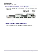
Страница 127: ...e Figure 6 11 Follow standard practices for Ethernet connections Use RJ45 connectors Use cable rated for Category 3 CAT3 or better Use straight cable wiring with identical pin connections on both plug ends Use twisted pair wires for receive pair and transmit pair Use continuity tester to verify pin connections Ethernet Jack Front View Twisted Pair Twisted Pair Ethernet Plug Wire Side Pins Pin 1 1 ...

Страница 128: ...ator Connect Ethernet cable to Ethernet connector on rear panel of Access Navigator Push plug in until it clicks in place Figure 6 12 Location of Ethernet Connector and Indicator Connect Ethernet Cable to Ethernet Hub Connect other end of Ethernet cable to an Ethernet hub or computer interface card Ethernet Connector Ethernet Link OK Status Indicator ...

Страница 129: ...tor for use with an external timing source such as a Building Integrated Timing Supply BITS to synchronize wireline transmissions Installation Summary n Tools and Materials 6 25 n Make BITS Cable Optional 6 26 n Connect BITS Cable 6 26 Tools and Materials Obtain the following tools and materials ANSI T1 403 RJ48C timing input cable or materials to make timing cable see Step 2 Continuity tester ...

Страница 130: ...t cable wiring with identical pin connections on both plug ends Use twisted pair wires for receive pair Use continuity tester to verify pin connections Figure 6 13 RJ48C Cable Construction Connect BITS Cable Connect RJ48C timing input cable to Timing In connector on rear panel of Access Navigator see Figure 6 14 Push plug in until it clicks in place Figure 6 14 Location of Timing Input BITS Connec...

Страница 131: ...ANGER OBSERVE EXTREME CAUTION IF FACILITY ALARM SYSTEM USES HIGH VOLTAGE WARNING DO NOT EXCEED MAXIMUM RELAY CONTACT RATINGS OF 1 AMPERE AT 110 VOLTS AC OR DC EXCESSIVE CURRENT OR VOLTAGE WILL DAMAGE THE RELAY CONTACTS IN THE ACCESS NAVIGATOR Tools and Materials Obtain the following tools and materials Pliers needle nose Cutters diagonal Wire stripper 16 26 AWG Continuity tester Volt ohm meter 16 ...

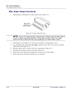
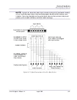
Страница 132: ...nt on these contacts until they are energized by the external alarm system 2 Refer Figure 6 16 and Figure 6 17 when wiring connector to facility alarm system 3 Use volt ohm meter to ensure that no voltage is present on any of the wires going to the facility alarm system see Figure 6 16 4 Strip the wires so that 5 16 inch of bare wire is exposed see Figure 6 17 5 Orient the alarm output connector a...

Страница 133: ... Alarm Facility Alarm System Output Alarm Connector on back panel Alarm Panel Normally open contacts Alarm Output Circuit MAXIMUM CONTACT RATING 1 Amp 110 V AC or DC Daisy chain Alarm Outputs from other Access Navigators Minor Alarm Pins 1 2 Major Alarm Pins 3 4 Critical Alarm Pins 5 6 Strip off insulation 5 16 inch This wire is connected correctly This wire is connected incorrectly bare wire is s...

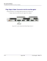
Страница 134: ...ector into Access Navigator Plug Output Alarm Connector into Access Navigator Plug connector into Access Navigator Alarm Out connector see Figure 6 18 Inspect connectors to ensure that no bare copper wire is exposed Figure 6 18 Location of Rear Panel Alarm Output Connector Alarm Out Connector ...

Страница 135: ...ENSURE DETECTION OF CONTACT CLOSURE LONG WIRES SHOULD BE SHIELDED TO PREVENT FALSE ALARMS FROM INDUCED VOLTAGES WARNING DO NOT APPLY EXTERNAL VOLTAGE TO ALARM INPUT CONNECTOR THIS INTERFACE IS DESIGNED FOR OPERATION WITH EXTERNAL SWITCHES OR RELAYS PROVIDING ISOLATED CONTACTS WITH MINIMUM CONTACT RATINGS OF 60V DC 10 MA Tools and Materials Obtain the following tools and materials Pliers needle nos...

Страница 136: ... 16 inch of bare wire is exposed see Figure 6 20 5 Orient the alarm output connector as shown in Figure 6 20 6 Insert wire into bottom opening then tighten screw above to clamp wire in place 7 Ensure that no bare wire shows after the wires are installed 8 Connect cable shield to Access Navigator chassis ground or to its equipment rack Do not ground both ends of shield Figure 6 20 Alarm Input Conne...

Страница 137: ...ze these wires so that a contact closure will produce a minor alarm indication and minor alarm message Figure 6 21 Typical Connections to Facility Alarm System Input Alarms Facility Alarm System Input Alarm Connector on back panel MAXIMUM OUTPUT 24 VDC open circuit 10 mA closed circuit Alarm Input Circuit Alarm Sensors 1 2 3 MAXIMUM LENGTH Loop resistance of cable must be less than 8 ohms CABLE SH...

Страница 138: ...Input Connector into Access Navigator Plug Alarm Input Connector into Access Navigator Plug connector into Access Navigator Alarm In connector Inspect connectors to ensure that no bare copper wire is exposed Figure 6 22 Location of Rear Panel Alarm Input Connector Alarm In Connector ...

Страница 139: ... IS ON CAUTION BOTH POWER CONNECTORS MUST BE WIRED AND CONNECTED TO POWER SOURCES FAILURE TO DO SO WILL DISABLE REDUNDANT SWITCHING FEATURES AND MAY INTERRUPT SERVICE WARNING POWER INPUT CONNECTORS ARE FOR 48V DC POWER ONLY Tools and Materials NOTE If the power connector is wired to a fuse panel use a 5 0 Amp slow blow fuse Obtain the following tools and materials Pliers needle nose Cutters diagon...

Страница 140: ... That way if a Controller card or power source fails the redundant Controller card is capable of powering all circuits in the Access Navigator If separate 48V DC power sources are not available then both power connectors must be wired to the same power source 1 Open package containing 3 pin power connectors 2 ea see Figure 6 23 Figure 6 23 Power Connector Wiring 2 Wire each connector to a 48V DC p...

Страница 141: ...ng into Access Navigator 2 Apply power to connector Replace fuse or turn on circuit breaker 3 Touch voltmeter probes to screw clamps below pins 2 and 3 of connector plug 4 Verify that voltage is between 42V and 58V DC 5 Verify that voltage is correct polarity 6 Turn off power to connectors Connect Power Plugs to Access Navigator 1 Plug connectors into Access Navigator power input connectors see Fi...

Страница 142: ...ce If desired use wire tie anchors on rear panel see Figure 6 25 to secure wires Ferrite bead RF suppressors may be moved slightly to allow for securing wire ties When mounted horizontally the ground wire and DSX 1 cables are normally dressed toward left side of rack and all other cables and wires are dressed toward right side as viewed from connector panel Figure 6 25 Ensure that no bare wires ar...

Страница 143: ... Connections 6 41 n Verify RS 232 Management Connection 6 42 n Verify Ethernet Cable Connection 6 43 n Verify Ethernet Management Connection 6 43 n Verify BITS Connection 6 44 n Verify Alarm Output Connections 6 45 n Verify Alarm Input Connections 6 47 n Exit Management Session 6 48 NOTE If connections appear to be correct but unit fails the verification requirements refer to Diagnostics Troublesh...

Страница 144: ...ghts green Requirement CONTROLLER A ACTIVE indicator lights green 2 If second redundant controller is present verify the following front panel status indications Requirement CONTROLLER B POWER indicator lights green Requirement CONTROLLER B ACTIVE indicator is off NOTE If power indicators do not light check power connections see DC Power Connections on page 6 35 Figure 6 26 Location of Front Panel...

Страница 145: ...eive input connectors The Access Navigator can be equipped with up to 32 DS1 interfaces 1 Establish temporary loopback or cross connect between DS1 receive and transmit signals at the DSX 1 interface or patch panel 2 Turn on 48 VDC power if not already on 3 Verify the following front panel status indications see Figure 6 27 Requirement DS1 status indicators light green for all installed circuit ca...

Страница 146: ...mation see CLI Language Reference on page 18 1 1 Turn on power to computer craft terminal and optional modem if used 2 Configure computer terminal emulation software or craft terminal as follows Terminal emulation ANSI ASCII VT100 Flow control None Send mode echo characters locally Baud rate 9600 Data bits 8 Parity None Stop bits 1 NOTE In the following step it is only important that the Access Na...

Страница 147: ...ve Ethernet hub or interface card Figure 6 28 Location of Ethernet Link Indicator Verify Ethernet Management Connection 1 Verify Ethernet operation by initiating a Telnet session to the Access Navigator s IP address This can also be done remotely from the network operations center The Access Navigator should respond with a message similar to the following If necessary press Return or Enter key to ...

Страница 148: ... clock1 and set clock2 commands 2 Enter following commands to assign the BITS input as the primary and secondary clock source set clock1 bits set clock2 bits 3 Display clock status status clock A message similar to the following will appear Primary Clock Source BITS Clock Status In Service Secondary Clock Source BITS Clock Status In Service NOTE If the Clock Status for BITS source shows Not in Ser...

Страница 149: ... functions as follows Enter the following command to simulate critical alarm set alarms critical on Requirement Critical alarm relay output contacts close see Figure 6 16 on page 6 29 Requirement Active Controller card Critical Alarm indicator lights Figure 6 30 Enter the following command to turn off critical alarm set alarms critical off Requirement Critical alarm relay output contacts open Requ...

Страница 150: ...f major alarm set alarms major off Requirement Major alarm relay output contacts open Requirement Active Controller card Major Alarm indicator goes off 3 Verify minor output alarm functions as follows Enter the following command to simulate minor alarm set alarms minor on Requirement Minor alarm relay output contacts close see Figure 6 16 on page 6 29 Requirement Active Controller card Minor Alarm...

Страница 151: ...input pair l 2 3 in Figure 6 31 to simulate an alarm contact closure See Alarm Input Connections on page 6 31 Requirement Contact closure on any alarm input wire pair produces Minor Alarm indica tion on active Controller card see Figure 6 32 Figure 6 31 Location of Rear Panel Alarm Input Connector Figure 6 32 Location of Active Controller and Minor Alarm Indicators NOTE If status indications are n...

Страница 152: ...xit Management Session Exit Management Session NOTE You will remain logged into the Access Navigator until you use the exit command When you are finished with the management session you must log out and exit from the Access Navigator by entering the following command exit ...

Страница 153: ... Verify Operation 6 53 n Replace Front Cover 6 54 Precautions DANGER BURN HAZARD CHASSIS COVER SCREWS AND CARDS MAY BE HOT TO THE TOUCH CAUTION SERVICE DISRUPTIONS MAY OCCUR IF TWO CONTROLLER CARDS ARE INSTALLED WITH INCOMPATIBLE SOFTWARE SUCH AS ONE DCS CARD AND ONE GR 303 CARD IF THE SOFTWARE IS NOT COMPATIBLE DO NOT SWITCH NEW CONTROLLER INTO ACTIVE MODE REMOVE CARD AND RETURN TO REPAIR FACILIT...

Страница 154: ... SOFTWARE ON page 17 1 NOTE This procedure assumes that the existing Controller is in card slot A and that the redundant Controller will be installed in card slot B If this is not true reverse the A and B designations in the following steps 1 If not currently logged into the Access Navigator initiate an RS 232 management session see Start RS 232 Management Session on page 7 6 2 Display version of ...

Страница 155: ...MPO NENTS THAT ARE SUBJECT TO DAMAGE BY ELECTROSTATIC DISCHARGE ESD ALWAYS FOLLOW THE STATIC SENSITIVE EQUIPMENT HANDLING PROCEDURES ON page 6 3 WHEN OPENING EQUIPMENT COVERS AND HANDLING PLUG IN CIRCUIT CARDS 1 Put on grounding wrist strap and follow anti static procedures 2 Loosen captive thumbscrews on front cover see Figure 6 33 3 Remove front cover and set aside Figure 6 33 Location of Front ...

Страница 156: ...Straighten card ejector latches see Figure 6 35 position Controller card in guide rails and carefully slide card into slot 3 Press card ejector latches in toward center of card until card connector mates with backplane connector Figure 6 34 Location of Controller Cards Figure 6 35 Installing Controller Card Controller A Controller B Card Ejector Latches B A Eject Lock ...

Страница 157: ...rement CONTROLLER A ACTIVE STANDBY indicator lights green Requirement CONTROLLER B ACTIVE STANDBY indicator is off 3 Display version of newly installed redundant Controller card by entering the following command status equipment A message similar to the following will appear Equipment Status Version Controller A Active 01 70 Controller B Standby 01 70 4 Is version of active Controller card compati...

Страница 158: ...roller B is now in active mode by entering following command status equipment Requirement Equipment status display shows Controller B is in Active mode NOTE If status indications are not correct refer to Diagnostics Troubleshooting on page 15 1 8 When you are finished with the management session you must log out and exit from the Access Navigator by entering the following command exit Replace Fron...

Страница 159: ...errupting service on other cards Installation Summary l Precautions 6 55 l Tools and Materials 6 55 l Remove Front Cover 6 56 l Install Quad T1 Framer Card 6 57 l Verify Operation 6 59 l Replace Front Cover 6 61 Precautions DANGER BURN HAZARD CHASSIS COVER SCREWS AND CARDS MAY BE HOT TO THE TOUCH WARNING THE ACCESS NAVIGATOR CONTAINS CIRCUIT CARDS AND COMPO NENTS THAT ARE SUBJECT TO DAMAGE BY ELEC...

Страница 160: ...MPO NENTS THAT ARE SUBJECT TO DAMAGE BY ELECTROSTATIC DISCHARGE ESD ALWAYS FOLLOW THE STATIC SENSITIVE EQUIPMENT HANDLING PROCEDURES ON page 6 3 WHEN OPENING EQUIPMENT COVERS AND HANDLING PLUG IN CIRCUIT CARDS 1 Put on grounding wrist strap and follow anti static procedures 2 Loosen captive thumbscrews on front cover see Figure 6 37 3 Remove front cover and set aside Figure 6 37 Location of Front ...

Страница 161: ...te next available Quad T1 Framer card slot see Figure 6 38 Figure 6 39 shows installation of QF card 6 1 Locate card slot in which to install Quad T1 Framer card see Figure 6 38 Figure 6 38 Location of Quad T1 Framer Cards QF Card 6 Circuits 21 24 QF Card 8 Circuits 29 32 QF Card 7 Circuits 25 28 QF Card 5 Circuits 17 20 QF Card 4 Circuits 13 16 QF Card 3 Circuits 9 12 QF Card 2 Circuits 5 8 QF Ca...

Страница 162: ...r and straighten card ejector latch see A in Figure 6 39 3 Position new QF card in guide rails and carefully slide into slot until it mates with backplane connector 4 Press card ejector latch in toward center of card see B in Figure 6 39 to secure card in card slot Figure 6 39 Installing Quad T1 Framer Card Card Ejector Latch Eject Lock B A ...

Страница 163: ...r Equipment Status Version Controller A Active 01 70 Controller B Standby 01 70 DS1 Card 1 Installed 1 DS1 Card 2 Installed 1 DS1 Card 3 Installed 1 DS1 Card 4 Installed 1 DS1 Card 5 Installed 1 DS1 Card 6 Installed 1 DS1 Card 7 Card not installed DS1 Card 8 Card not installed Requirement Equipment status shows DS1 card is installed NOTE If status display shows that the card is not installed check...

Страница 164: ...on of DS1 Status Indicators 6 Display status of DS1s on Quad T1 Framer card by entering the following command status ds1 n A message similar to the following will appear for each DS1 Status for DS1 1 Receive Traffic Transmit Traffic Requirement DS1 status display shows Traffic in receive and transmit directions 7 Remove DS1 loop back at patch panel 8 If required set DS1s on Quad T1 Framer card out...

Страница 165: ... and tighten screws Configure Management Interfaces This procedure provides steps for setting up the RS 232 and Ethernet interface configurations for remote management by CLI Telnet SNMP Valet and NetworkValet EMS software Setup Summary n Start RS 232 Management Session 6 62 n Set Date 6 63 n Set Time 6 63 n Set System ID or CLLI code 6 64 n Set IP Address and Subnet Mask 6 64 n Set Gateway Addres...

Страница 166: ...d messages For additional information see CLI Language Reference on page 18 1 1 Configure computer terminal emulation software or craft terminal as follows Terminal emulation ANSI ASCII VT100 Flow control None Send mode echo characters locally Baud rate 9600 Data bits 8 Parity None Stop bits 1 NOTE In the following step it is only important that the Access Navigator respond with a message A typica...

Страница 167: ...mand show date Requirement Access Navigator responds with correct date Set Time NOTE Time format is 24 hour clock in hours minutes seconds with colons to separate the digits as in 08 30 45 and 15 22 10 1 Set current time by entering the following command set time hh mm ss Example set time 08 30 45 The time will be updated when you press the Enter or Return key and the Access Navigator receives the...

Страница 168: ...tion must be used to set up the Ethernet port for remote management by Telnet SNMP Valet or NetworkValet EMS software NOTE IP Address Each Access Navigator on the same Ethernet network must have a unique static Internet Protocol IP address IP addresses have the format xxx xxx xxx xxx where each xxx is a decimal number between 0 and 255 For example 192 168 0 123 is a valid IP address Note that the ...

Страница 169: ...s from one network to another network in their trip across the Internet Gateway addresses have the same format as IP addresses If a gateway address is not used you must enter none for the gateway address Set the gateway IP address by typing the following line after the prompt then press the Enter or Return key set ip gateway address If the gateway address is not used enter set ip gateway none To d...

Страница 170: ...6 66 August 2003 Access Navigator Release 1 8 Electrical Installation Exit Management Session ...

Страница 171: ...ER Start Management Session In this Chapter n Management Requirements 7 2 n Command Line Interface Conventions 7 3 n RS 232 Management 7 4 n Telnet Management 7 8 n NetworkValet EMS and Valet Management 7 11 ...

Страница 172: ...ment Connection on page 6 22 l RS 232 CLI Management requires an RS 232 connection to the Access Navigator l Telnet CLI Management requires an Ethernet connection to the Access Navigator The Ethernet function can only be turned up through the RS 232 management interface l SNMP Management requires an Ethernet connection to the Access Navigator The SNMP function can only be turned up through the RS ...

Страница 173: ...r in a bold typewriter font as in the following example set ds1 1 4 up l If a command requires the operator to enter information an italic typewriter font is used to show what item or items are required Each item will be enclosed in and symbols as in the following example Do not type the symbols set ds1 n setting l If the operator must enter one item from a list the items will be separated by vert...

Страница 174: ...th terminal emulation software The Access Navigator operating system provides a Command Line Interface CLI which uses simple text based commands and messages See Command Line Interface Conventions on page 7 3 for a short description of the conventions used in this manual to represent management commands settings and messages For detailed information see CLI Language Reference on page 18 1 Procedur...

Страница 175: ...S 232 DCE to DTE cable with 9 pin DE9 DB9 connector on one end to RS 232 CLI management connector on rear panel of Access Navigator see Figure 7 1 3 Connect other end of RS 232 cable to computer or craft terminal Figure 7 1 Location of RS 232 CLI Connector Set Up Terminal Program Configure computer terminal emulation software or craft terminal as follows Terminal emulation ANSI ASCII or VT100 Flow...

Страница 176: ...irst management session after installation Command prompts always end with the symbol The default command prompt is Access Navigator The command prompt indicates that the system is waiting for the operator to enter the next command However if the previous command was rejected an error message will appear immediately above the prompt to describe the error or show the position of the first rejected ...

Страница 177: ...uired by the installation provisioning or maintenance procedure For detailed command descriptions see CLI Language Reference on page 18 1 Exit RS 232 Management Session NOTE You will remain logged into the Access Navigator until you use the exit command When you are finished with the management session you must log out and exit from the Access Navigator by entering the following command exit ...

Страница 178: ... for a short description of the conventions used in this manual to represent management commands settings and messages For detailed information see CLI Language Reference on page 18 1 NOTE You will remain logged into the Access Navigator until you terminate the management session by using the exit command If you do not terminate the session before disconnecting from the Telnet server the Access Na...

Страница 179: ...t management session by pressing the Enter or Return key NOTE When a management session is started the Access Navigator will either request a user login name or display a command prompt A Login request indicates that security features have been activated The operator must enter a valid user name in order to proceed any further A user password may also be required Whenever a login name or password ...

Страница 180: ...avigator Perform Management Operations After logging on perform whatever management operations are required by the installation provisioning or maintenance procedure For detailed command descriptions see CLI Language Reference on page 18 1 Exit Telnet Management Session When Finished NOTE You will remain logged into the Access Navigator until you terminate the session by using the exit command If ...

Страница 181: ...s NOCs NetworkValet and Valet provide easy management of Carrier Access products including the Access Navigator and Adit 600 Valet and NetworkValet are cross platform Java applications that run on either Microsoft Windows and Solaris based computer systems Java Runtime Engine JRE software for Windows or Solaris is included with the Valet and NetworkValet installation programs NetworkValet and Vale...

Страница 182: ...7 12 August 2003 Access Navigator Release 1 8 Start Management Session NetworkValet EMS and Valet Management ...

Страница 183: ...w 8 2 n Basic Provisioning Quick Guide 8 2 n Obtain Provisioning Information 8 3 n Verify System Equipment Configuration 8 4 n Set System ID or CLLI Code 8 5 n Set Date 8 6 n Set Time 8 6 n Set Ethernet Properties 8 7 n Set User and Password Security 8 9 n Set SNMP Properties 8 11 ...

Страница 184: ...ves setting up the Access Navigator for network operation and remote management Basic provisioning includes the following items CLI Commands Descriptions status equipment Verify system configuration set id id System Identifier or CLLI code set date mm dd yyyy Date with four digit year set time hh mm ss Time with 24 hour clock set ethernet ip address none set ethernet ip address address mask set ip...

Страница 185: ...ormation as needed Office records for installation site System Name or CLLI code Ethernet IP address Ethernet Subnet mask Gateway address User names and passwords SNMP System Name or CLLI code SNMP System Location SNMP System Contact SNMP Get Community string SNMP Set Community string SNMP Trap Community string SNMP Trap NMS Recipients up to three IP addresses ...

Страница 186: ...nt Session on page 7 1 2 Show system equipment configuration with the following command status equipment A message similar to the following will appear showing the equipment card slots service status and Controller software version Equipment Status Version Controller A Active 01 00 Controller B Standby 01 00 DS1 Card 1 Installed 1 DS1 Card 2 Installed 1 DS1 Card 3 Installed 1 DS1 Card 4 Installed ...

Страница 187: ...osed in quote marks NOTE The System Identifier also appears in the command line prompt The default System Identifier is Access Navigator so the command prompt will be Access Navigator When you change the identifier the prompt will also change If other management sessions are in progress the operators will not see the new prompt until they start a new session 1 Show current System Identifier with t...

Страница 188: ...h the following command set date mm dd yyyy Example set date 01 30 1999 Set Time NOTE Time format is 24 hour clock in hours minutes seconds with colons to separate the digits as in 08 30 45 and 15 22 10 1 Show current time setting with the following command show time 2 If time setting is correct skip remaining steps 3 Set correct time with the following command set time hh mm ss Example set time 0...

Страница 189: ... NOTE Subnet Mask The Access Navigator uses a subnet mask to identify the permissible range of IP addresses on the local network Large networks are usually divided into smaller subnetworks each with an assigned range of IP addresses Addresses outside the subnetwork will be directed to the Gateway address Subnet masks have the format xxx xxx xxx xxx where each xxx is a decimal number between 0 and ...

Страница 190: ...wing command set ethernet ip address address mask Example set Ethernet address 192 168 118 65 255 255 255 0 To turn off Ethernet interface enter set ethernet ip address none 4 If gateway IP address is not correct enter the following command set ip gateway address Example set ip gateway 192 168 118 65 If there is no gateway address enter set ip gateway none ...

Страница 191: ...8 Bill 1 14 06 25 11 17 1998 CarlSmith 2 11 17 45 11 22 1998 Dave46 3 12 14 33 11 20 1998 2 If user settings correct are correct skip remaining steps NOTE User names can be up to 10 characters long and may use any combination of letters and numbers Spaces and special characters are not allowed 3 Add new user names with the following command add user name Example add user Alice NOTE All users have ...

Страница 192: ...lower case letters are different 5 Set user passwords with the following command set user name password Example set user Alice password The system will prompt you to enter a new password twice for verification To ensure security password characters are displayed as asterisks To delete a user password so that the user has access without a password press Enter or Return key each time the system prom...

Страница 193: ... NMS 1 192 168 0 65 NMS 2 NMS 3 2 If SNMP settings are correct skip remaining steps 3 Set SNMP System Name or Identification code with the following command set snmp name setting Example set snmp name Acme Corp AN 2 NOTE Telcordia Bellcore Common Language Location Identifier CLLI codes are text strings with up to 11 characters 4 Set SNMP System Location or CLLI code with the following command set ...

Страница 194: ...nmp trapcom setting Example set snmp trapcom Public NOTE SNMP trap alarm messages can be sent to three different host IP addresses Repeat the following command to set the IP address of each recipient 9 Set up to three SNMP NMS network management system trap recipients by entering their IP addresses with the following command set snmp nms 1 2 3 address Example set snmp nms 1 192 168 118 65 ...

Страница 195: ...ervice Status 9 8 n Set Unused Circuits Out of Service 9 10 n Set System Clock Source 9 11 n Provision Groom DS1 Circuits to Network 9 12 n Test Groom DS1 Circuits 9 14 n Provision Drop DS1 Circuits to Subscribers 9 14 n Provision and Connect ISDN PRI Channels 9 16 n Provision and Connect ISDN BRI 3DS0 Channels 9 16 n Provision and Connect DS0s 9 17 n Turn Up Service 9 19 n Test DS1 and DS0 Circui...

Страница 196: ...ess Navigator Ethernet Telnet SNMP Data Network Voice Switch Groom T1s Internet Data Private and Special Services DCS Voice and Data Voice Public Network 24 Lines PBX Key System Modem Fax Stations Access Bank I Voice ACCESS BAN K I Tip Ring 4 8Vdc Return Ground T1 Framing Outp ut Moni tor Input Monitor Alarm Cut O ff T1 Test Netw ork Loopback Norm al Normal Normal Self Test Normal Rem ote Statu s ...

Страница 197: ...5 for the D channel by multiplexing four D channels onto one DS0 This mode can efficiently carry 4 BRIs using only 9 DS0s This mode works with GR 303 switch interfaces using a fixed connection for the D channel and dynamically connecting the two B channels when needed The Access Navigator DCS supports ISDN BRI service also called 2B D using the 3DS0 mode in which the two Bearer channels B1 and B2 ...

Страница 198: ...t of the Access Bank II See Provision Remote Access Bank II on page 11 1 A TR 08 SLC 96 compatible switch connects to the Access Navigator groom DS1s using D4 framing equivalent to SLC 96 SF framing By crossconnecting the voice channels at the DS0 level the Access Navigator is able to groom and fill the DS1s going to the TR 08 switch for most efficient use of DS1 resources DCS also works with drop...

Страница 199: ...08 Shelf B C D support requires the following settings for the DS1 drop and groom lines For other DCS settings see Provisioning TR 08 Service with DCS on page 9 3 CLI Commands TR 08 Item Descriptions set ds1 n framing d4 set ds1 n framing esf DS1 drop to TR 08 channel bank DS1 drop to remote Access Bank II set ds1 n framing d4 DS1 groom to TR 08 switch set ds0 n ch type voice set ds0 n ch type dat...

Страница 200: ...at the other end of the DS1 set clock1 bits ds1 n internal Primary system clock source set clock2 bits ds1 n internal Secondary system clock source set ds1 n type groom drop DS1 type set ds1 n framing d4 esf DS1 framing set ds1 n linecode ami b8zs DS1 line code set ds1 n id id DS1 identifier set ds1 n clock normal loop DS1 clock source set ds1 n lbo setting DS1 line buildout set ds1 n loopdetect o...

Страница 201: ... CIRCUITS 1 Start management session see Start Management Session on page 7 1 2 Show system equipment configuration with the following command status equipment A message similar to the following will appear showing the equipment card slots service status and Controller software version and options Equipment Status Version Controller A Active 01 70 Controller B Standby 01 70 DS1 Card 1 Installed 1 ...

Страница 202: ...1 12 DOWN DROP B8ZS ESF None None CA DS1 13 DOWN DROP B8ZS ESF None None CA DS1 14 DOWN DROP B8ZS ESF None None CA DS1 15 DOWN DROP B8ZS ESF None None CA DS1 16 UP DROP AMI D4 None None CA DS1 17 UP DROP AMI D4 None None CA DS1 18 UP DROP B8ZS SLC96 None SLC96 CA DS1 19 UP DROP B8ZS SLC96 None None CA DS1 20 UP DROP B8ZS ESF T1403 None CA DS1 21 UP GROOM B8ZS ESF None None CA DS1 22 UP GROOM B8ZS ...

Страница 203: ...raffic Loop None State In Service FDL type None Status for DS1 29 Receive Traffic Transmit Traffic Loop None State Card Not Installed FDL Type None 5 Verify status of DS1 lines to be turned up by comparing DS1 status with office records If there is a discrepancy follow standard practices to resolve problem NOTE Commands containing ds0 n ch require the operator to enter both the DS1 and DS0 channel...

Страница 204: ... DS0 status with office records If there is a discrepancy follow standard practices to resolve problem Set Unused Circuits Out of Service NOTE The factory default sets all DS1s and DS0s in service up To prevent inadvertent service disruptions it is good practice to set circuits out of service down when not in use or not provisioned in the switch Set unused DS1s out of service down Set the type of ...

Страница 205: ...rce DS1 1 Secondary Master Transmit Clock Source DS1 25 2 If clock settings are correct skip remaining steps 3 If primary clock setting is incorrect set clock1 source with the following command set clock1 setting Example set clock1 bits There are three different settings which are defined as follows Setting Definition bits Select external or BITS source on Timing In connector ds1 n Select clock re...

Страница 206: ...tion OFF Loop Back OFF Line Termination ID 0 for switch DS1s only FDL Type CAC Send Code None Performance Thresholds 15 min 1 hour 1 day unavailable seconds 0 0 0 severely errored seconds 0 0 0 errored seconds 0 0 0 sev errored frame seconds 0 0 0 degraded minutes 0 0 0 linecode violations 0 0 0 NOTE In the above message loop back test function is turned off and the send code set to none during no...

Страница 207: ...l loop Example set ds1 10 clock normal 8 Set groom DS1 line buildout lbo to required DSX 1 equalization or CSU attenuation with the following command set ds1 n lbo setting Example set ds1 10 lbo 3 The setting is a number from 1 to 9 and is defined as follows Setting Definition 1 Set DSX 1 equalization for 0 133 ft 2 Set DSX 1 equalization for 133 266 ft 3 Set DSX 1 equalization for 266 399 ft 4 Se...

Страница 208: ...example the message for DS1 number 20 might look similar to the following Settings for DS1 10 Circuit ID CA DS1 20 Up Down DOWN Framing ESF Line Coding B8ZS Type DROP Clock Source NORMAL Line Build Out DSX 1 EQUALIZATION FOR 0 133 ft Loop Code Detection OFF Loop Back OFF Line Termination ID 0 for switch DS1s only FDL Type CAC Send Code None Performance Thresholds 15 min 1 hour 1 day unavailable se...

Страница 209: ...et ds1 n clock normal loop Example set ds1 20 clock normal 8 Set drop DS1 line buildout lbo to required DSX 1 equalization or CSU attenuation with the following command set ds1 n lbo setting Example set ds1 20 lbo 8 The setting is a number from 1 to 9 and is defined as follows Setting Definition 1 Set DSX 1 equalization for 0 133 ft 2 Set DSX 1 equalization for 133 266 ft 3 Set DSX 1 equalization ...

Страница 210: ...B23 and the signaling channel D All PRI channels must be set to the DS0 Type Data Provision and Connect ISDN BRI 3DS0 Channels ISDN BRI service using 3DS0 transport mode is provisioned and connected in the same way as other DS0 data channels described on the following pages except that each ISDN BRI requires three DS0s For each ISDN BRI to be provisioned the operator must create crossconnections f...

Страница 211: ...10 04 GR303 10 05 GR303 10 06 GR303 10 07 GR303 10 08 GR303 10 09 25 17 GR303 10 10 GR303 10 11 GR303 10 12 GR303 10 13 10 14 10 15 10 16 10 17 09 12 DATA AcmeInternet V 35 10 18 09 13 DATA AcmeInternet V 35 10 19 09 14 DATA AcmeInternet V 35 10 20 09 15 DATA AcmeInternet V 35 10 21 09 16 DATA AcmeInternet V 35 10 22 09 17 DATA AcmeInternet V 35 10 23 09 18 DATA AcmeInternet V 35 10 24 09 19 DATA ...

Страница 212: ...signaling voice only to Loop Start ls Ground Start gs or E M em signaling with the following command set ds0 n ch signal ls gs em Example set ds0 10 1 18 signal gs 6 Connect DS0s see crossconnect examples in Figure 9 4 to make 2 way connections between DS0s or fractional groups of DS0s with the following command connect n ch n ch Example connect 10 19 24 5 1 6 Figure 9 4 Crossconnect Examples conn...

Страница 213: ...ettings are correct skip remaining steps 4 Set DS1s and DS0s to in service up status with the following commands set ds1 n up set ds0 n ch up Example set ds1 5 up Example set ds0 5 1 6 Test DS1 and DS0 Circuits NOTE The Access Navigator supports the following T1 403 loop tests Responds to ESF bit patterned loop requests when loopdetect is on Generates ESF bit patterned loop requests Generates SF C...

Страница 214: ...9 20 August 2003 Access Navigator Release 1 8 Provision DCS Service Test DS1 and DS0 Circuits ...

Страница 215: ...t System Switch Type 10 14 n Set System Clock Source 10 14 n Provision Switch DS1s to Interface Group 10 15 n Assign Primary and Secondary EOC 10 18 n Assign Primary and Secondary TMC 10 19 n Test DS1 Circuits 10 20 n Provision Drop DS1 Circuits to Subscriber 10 21 n Provision ISDN BRI 4 1 TDM Service to Subscribers 10 25 n Provision DS0s to Subscribers 10 30 n Assign Call Reference Values CRVs 10...

Страница 216: ... system the Central Office switch is the Integrated Digital Terminal IDT and the Access Navigator and Access Banks function as the Remote Digital Terminal RDT The switch communicates with the Access Navigator using an Embedded Operations Channel EOC and Timeslot Management Channel TMC in the GR 303 Interface Group The switch sets up crossconnects in the Access Navigator between switch DS0s drop DS...

Страница 217: ...p Ring 48Vdc Return Gr ound T1 Frami ng Output Monitor Input Moni tor Alarm Cut O ff T1 Tes t Network Loop back Normal Norm al Norm al Self Test Norm al Remote Status Key System Fax V 35 T1 or DSL Router Ethernet PBX Stations Access Bank II Voice and Data Voice Lines ACCESS BANK II Tip Ring 48Vdc Return Gr ound T1 Span 1 T1 Tes t2 T1 Test 1 T1 Span 2 V 35 DCE V 35 Statu s RS23 2 Data Adit 600 Voic...

Страница 218: ...ls of four BRI connections into one DS0 channel that is statically connected to the switch In the 4 1 TDM mode the switch uses Call Reference Values CRVs to set up ISDN BRI connections for the B1 and B2 bearer channels For 3DS0 transport mode using DCS see Provisioning ISDN BRI Service on page 9 3 Provisioning P Phone Service The Nortel Proprietary Phone P Phone also called an Electronic Business ...

Страница 219: ...SLC 96 type digital loop carrier systems with TR 08 interfaces to newer systems with GR 303 interfaces see Figure 10 2 In addition the Access Navigator can perform GR 303 call concentration and DCS grooming for data services Figure 10 2 Provisioning TR 08 Service to Access Banks Data Switch 24 Access Bank I TR 08 Access Navigator GR 303 Voice Switch DS1s GR 303 Interface Group Voice Switch Drop DS...

Страница 220: ...Bank II must be configured as Shelf B C or D with the DS1 link framing set to D4 Access Navigator DS1 drop framing must be set to slc96 to provide GR 303 to TR 08 translation NOTE The Access Bank II must have Controller card software version 2 26 or higher to support TR 08 Remote provisioning is not possible with D4 framing so Remote Monitor software version 2 04 or higher is needed to provision t...

Страница 221: ...CRVs in Odd Even Order 9 10 11 12 13 14 15 16 DS0 111 112 113 114 115 116 117 118 CRV Example Command set ds0 4 9 16 crv 111 118 Sequential Order 1 2 3 4 5 6 7 8 9 10 11 12 13 14 15 16 17 18 19 20 21 22 23 24 DS0 311 312 313 314 315 316 317 318 319 320 321 322 323 324 325 326 327 328 329 330 331 332 333 334 CRV Example Command set ds0 4 1 24 crv 311 334 slc96 Odd DS0s Even DS0s First 12 CRVs Last ...

Страница 222: ...nnections between shelves alarm monitoring is only available for Shelf A If desired all units can be configured as Shelf A when using GR 303 to TR 08 translation Special TR 08 Settings GR 303 provisioning for TR 08 Shelf B C D support requires the following settings for the DS1 drop lines Other GR 303 settings remain the same See GR 303 Provisioning Quick Guide on page 10 9 Switch 4 Switch 6 Shelf...

Страница 223: ...ce set switch type 5ess dms generic Ensures switch compatibility set ds1 n type switch groom drop DS1 type set ds1 n framing d4 esf slc96 DS1 framing set ds1 n linecode ami b8zs DS1 line code set ds1 n id id DS1 identifier set ds1 n termid id Switch DS1 terminal identifier set ds1 n clock normal loop DS1 clock source set ds1 n lbo setting DS1 line buildout set ds1 n fdl none slc96 t1403 DS1 FDL ty...

Страница 224: ...r end of the DS1 If the DS1 is not terminated set the type to data 1 Start management session see Start Management Session on page 7 1 2 Show system equipment configuration with the following command status equipment A message similar to the following will appear showing the equipment card slots service status and Controller software version Equipment Status Version Controller A Active 01 70 GR 30...

Страница 225: ... ESF None None CA DS1 08 DOWN DROP B8ZS ESF None None CA DS1 09 UP DROP B8ZS ESF None CA FDL CA DS1 10 UP DROP B8ZS ESF None CA IP CA DS1 11 DOWN DROP B8ZS ESF None None CA DS1 12 DOWN DROP B8ZS ESF None None CA DS1 13 DOWN DROP B8ZS ESF None None CA DS1 14 DOWN DROP B8ZS ESF None None CA DS1 15 DOWN DROP B8ZS ESF None None CA DS1 16 UP DROP AMI D4 None None CA DS1 17 UP DROP AMI D4 None None CA D...

Страница 226: ...S1 or range of DS1s to be turned up status ds1 n Example status ds1 1 This command will produce a message listing the status of the specified DS1 or range of DS1s For example the message for DS1 1 and 29 might look similar to the following Note that the message for DS1 1 shows the DS1 is in service while the message for DS1 29 indicates there is no Quad Framer circuit card installed Status for DS1...

Страница 227: ...r DS1 1 DS0 channels 1 to 4 and DS1 32 DS0 channels 1 to 4 would look similar to the following Interface Status DS1 1 Channel 1 In Service DS1 1 Channel 2 In Service DS1 1 Channel 3 In Service DS1 1 Channel 4 Out of Service DS1 32 Channel 1 Card Not Installed DS1 32 Channel 2 Card Not Installed DS1 32 Channel 3 Card Not Installed DS1 32 Channel 4 Card Not Installed 7 Verify status of DS0 circuits ...

Страница 228: ...terface Group 1 Show current clock settings with the following command show clock This command will produce a message similar to the following Primary Master Transmit Clock Source DS1 25 Secondary Master Transmit Clock Source DS1 29 2 If clock settings are correct skip remaining steps 3 Set clock primary clock1 source with the following command set clock1 setting Example set clock1 bits There are ...

Страница 229: ... Loop Code Detection OFF Loop Back OFF Line Termination ID 1 for switch DS1s only FDL Type NONE Send Code NONE Performance Thresholds 15 min 1 hour 1 day unavailable seconds 0 0 0 severely errored seconds 0 0 0 errored seconds 0 0 0 sev errored frame seconds 0 0 0 degraded minutes 0 0 0 linecode violations 0 0 0 NOTE In the above message loop back is a test function that is turned off during norma...

Страница 230: ... different installation configurations The Access Navigator provides the following default termination IDs for DS1s 25 to 32 so that termination IDs 1 and 2 are on different Quad T1 Framer cards for added protection DS1 25 termid 1 DS1 26 termid 3 DS1 27 termid 4 DS1 28 termid 5 DS1 29 termid 2 DS1 30 termid 6 DS1 31 termid 7 DS1 32 termid 8 NOTE To avoid duplication when setting line termination ...

Страница 231: ...ation for LBO of 22 5dB NOTE When loop request detection is turned on the Access Navigator will respond to T1 403 ESF bit patterned loop requests Detection is normally turned on for switch and groom DS1s and turned off for drop DS1s This allows higher level equipment to test the Access Navigator and allows the Access Navigator to test remote CSUs such as Access Banks 10 Set switch DS1 loop code de...

Страница 232: ...ault DS1 25 is TermID 1 and DS1 29 is TermID 2 The show ds1 all command lists the DS1 TermIDs 2 If switch EOC settings are correct skip remaining steps NOTE It is recommended that primary and secondary EOC and TMC be assigned to different Quad T1 Framer QF cards for added protection In the event one QF card fails the GR 303 switch will then be able to continue service using the redundant EOC and T...

Страница 233: ...5 is TermID 1 and DS1 29 is TermID 2 The show ds1 all command lists the DS1 TermIDs 2 If switch TMC settings are correct skip remaining steps NOTE It is recommended that primary and secondary EOC and TMC be assigned to different Quad T1 Framer QF cards for added protection In the event one QF card fails the GR 303 switch will then be able to continue service using the redundant EOC and TMC on a di...

Страница 234: ...sts Generates SF CSU inband loopcodes NOTE The Access Navigator provides line and payload loopback commands for troubleshooting line problems See Diagnostics Troubleshooting on page 15 1 NOTE If the Access Navigator is connected to the local digital switch you can use the status eoc and status tmc commands to determine the link status Up status indicates the LAPD communications link with the switc...

Страница 235: ...1 1 PPHONE Call Connection Enabled FDL Type None P Phone In Service Send Code NONE Performance Thresholds 15 min 1 hour 1 day unavailable seconds 0 0 0 severely errored seconds 0 0 0 errored seconds 0 0 0 sev errored frame seconds 0 0 0 degraded minutes 0 0 0 linecode violations 0 0 0 NOTE In the above message loop back is a test function that is turned off during normal service Line Termination I...

Страница 236: ...TR 08 translation must operate as Shelf B C or D Remote provisioning of an Access Bank II requires esf framing and cafdl protocol 4 Set drop DS1 frame type to D4 ESF or SLC 96 with the following command set ds1 n framing d4 esf slc96 Example set ds1 9 framing esf 5 Set drop DS1 line code to AMI or B8ZS with the following command set ds1 n linecode ami b8zs Example set ds1 9 linecode b8zs 6 Set dro...

Страница 237: ...her level equipment to test the Access Navigator and allows the Access Navigator to test remote CSUs such as Access Banks 9 Set drop DS1 loop code detection to on or off with the following command set ds1 n loopdetect on off Example set ds1 9 loopdetect off NOTE The Facility Data Link FDL channel is a 4 Kbps out of band communications link provided by the DS1 Extended Superframe ESF format The fac...

Страница 238: ...nly one management DS1 to a remote Adit 600 so all other DS1s to that Adit 600 must be set to point to the management DS1 See Provision Remote Adit 600 via FDL on page 12 1 and Provision Remote Adit 600 via IP DS0 on page 13 1 11 Set drop DS1 remote device management protocol to none Carrier Access FDL Carrier Access IP or a DS1 with the following command set ds1 n remote device mgmt none cafdl ca...

Страница 239: ...rating the numbers For example the channel list for DS1 4 and DS0 channel 8 would be entered as ds0 4 8 The channel list may also contain a range of DS0 channels For example DS1 6 and DS0 channels 1 through 12 would be entered as ds0 6 1 12 A colon follows the DS1 number and the beginning and ending DS0 channels are separated by a hyphen 1 Show current drop DS0 settings with the following command ...

Страница 240: ...ecified For example the message for showing ISDN CRVs 1 to 8 would look similar to the following CRV B1 B2 D 1 10 1 10 2 10 24 2 10 3 10 4 10 24 3 10 5 10 6 10 24 4 10 7 10 8 10 24 5 not assigned not assigned 10 23 6 not assigned not assigned 10 23 7 CRV not assigned to ISDN 8 CRV not assigned to ISDN NOTE The above message shows that CRVs 1 to 4 are assigned to ISDN BRI and that their B1 B2 and D...

Страница 241: ...t ds0 n ch isdn b1 b2 d crv range Example set ds0 10 1 isdn b1 crv 1 Example set ds0 10 2 isdn b2 crv 1 Example set ds0 10 3 isdn b1 crv 2 Example set ds0 10 4 isdn b2 crv 2 Example set ds0 10 24 isdn d crv 1 2 3 4 NOTE If RDT provisioning is enabled in the switch the switch can upload the ISDN CRVs and provision the ISDN D channel DS0s without requiring a switch operator to manually enter this in...

Страница 242: ...GR303 10 07 GR303 10 08 GR303 10 09 25 17 GR303 10 10 GR303 10 11 GR303 10 12 GR303 10 13 10 14 10 15 10 16 10 17 09 12 DATA AcmeInternet V 35 10 18 09 13 DATA AcmeInternet V 35 10 19 09 14 DATA AcmeInternet V 35 10 20 09 15 DATA AcmeInternet V 35 10 21 09 16 DATA AcmeInternet V 35 10 22 09 17 DATA AcmeInternet V 35 10 23 09 18 DATA AcmeInternet V 35 10 24 09 19 DATA AcmeInternet V 35 NOTE The abo...

Страница 243: ... To change existing ISDN BRI connections you must first disconnect them before making new connections 9 Disconnect existing ISDN BRI connections with the following command disconnect n ch Example disconnect 10 9 10 Connect ISDN BRI D channel to switch DS1 with the following command connect n ch n ch Example connect 10 9 25 17 ...

Страница 244: ...ttings with the following command show ds0 n ch Example show ds0 13 1 4 The show command will display the settings for each DS0 specified For example the message for showing DS1 number 13 DS0 channels 1 to 4 would look similar to the following Settings for DS1 13 Channel 1 Type GR303 Signaling LOOP START Up Down UP CRV 35 PPHONE Enabled ISDN None Settings for DS1 13 Channel 2 Type GR303 Signaling ...

Страница 245: ...ncentration on GR 303 interface groups to switches such as the Lucent 5ESS Two way DOD DID is not supported If the switch does not support GR 303 DID services the DID circuits can be groomed to a DS1 going to a DID shelf in the Central Office 4 For GR 303 Direct Inward Dial DID set DS0 signal to did with the following command set ds0 n ch signal did Example set ds0 13 2 signal did NOTE P Phone ser...

Страница 246: ...CRV numbers The only requirement is that the CRVs must be different for all assigned GR 303 voice terminations ISDN BRI connections use the same CRV for the B1 B2 and D channel NOTE A CRV with an active call can not be moved or reassigned NOTE To avoid duplication when setting CRV numbers if another channel has the same CRV number it will be set to CRV 0 not assigned 1 Show current CRV settings wi...

Страница 247: ...TE CRVs must be different for all assigned GR 303 voice terminations on drop DS0s Other CRVs will be ignored NOTE In the following command there must be an equal number of channels and CRVs 3 Set DS0 CRV range with the following command set ds0 n ch crv range Example set ds0 2 1 4 crv 118 121 DS1 1 DS0 1 Access Navigator DS0 24 DS1 2 DS0 1 DS0 24 DS1 32 DS0 1 DS0 24 CRV 1 CRV 24 CRV 25 CRV 48 CRV ...

Страница 248: ...s with the following commands set ds1 n up set ds0 n ch up Example set ds1 13 up Example set ds0 13 1 16 up Test Circuits NOTE The Access Navigator supports the following T1 403 loop tests Responds to ESF bit patterned loop requests when loopdetect is on Generates ESF bit patterned loop requests Generates SF CSU inband loopcodes NOTE The Access Navigator provides line and payload loopback commands...

Страница 249: ...11 14 n Provision Drop DS1 to Remote Access Bank II 11 15 n Test DS1 Circuits 11 17 n Provision DS0s 11 17 n Provision DS0 Crossconnects 11 19 n Create Fractional Interfaces if required 11 21 n Configure Remote RS 232 Interface if used 11 22 n Configure Remote T1 Drop Interface if used 11 24 n Configure Remote V 35 Interface if used 11 26 n Connect Fractional Interface to Remote Interface 11 28 n ...

Страница 250: ...rovisioning feature enables the operator to remotely provision voice and data services at any time even before the Access Bank II is installed on the customer premises When the Access Bank II is installed and powered up the Access Navigator when configured for Carrier Access FDL cafdl remote management automatically senses the DS1 connection and downloads provisioning data over the FDL channel of ...

Страница 251: ...ased by remote downloads For remote provisioning the DS1 drop on the Access Navigator must be provisioned for ESF framing B8ZS line code and Carrier Access FDL CAFDL remote management On the Access Bank II the T1 interface must be set to ESF framing B8ZS line code and PRM protocol AT T 54016 which are the default settings To support remote provisioning the Access Bank II family requires Controller...

Страница 252: ...ssconnect Features The Access Bank II contains DS0 crossconnect switches that are remotely controllable This enables the Access Navigator to set up connections between the DS1 drop DS0s and the various Access Bank II voice and data interfaces Internal crossconnections can also be made between the Access Bank s T1 Drop port and other remote interfaces such as the V 35 port The operator specifies wh...

Страница 253: ...03 FX analog Valid Valid RS 232 Valid SDSL Valid T1 Drop Valid Valid Valid V 35 Valid DS0s 1 24 FX Card 1 RS 232 T1 Drop or SDSL V 35 Default Settings connect DS0s 1 to 24 to FX channels 1 to 24 No remote inter faces are connected A DS0s 1 24 RS 232 T1 Drop or SDSL V 35 When DS0s are connected to a remote interface the remaining voice and GR 303 DS0s are connected to the corresponding FX channels ...

Страница 254: ...ms and other analog voice terminations see Figure 11 4 The Access Navigator connects any unassigned voice or GR 303 DS0s to the FX interface If no remote interfaces are used DS0 channels 1 to 24 will be connected to FX channels 1 to 24 as in example A in Figure 11 3 If you connect DS0s to a remote interface the Access Navigator will connect the remaining voice or GR 303 DS0s to the FX channels as ...

Страница 255: ...carry GR 303 voice service the Access Navigator must have the GR 303 option to make connections to a GR 303 IDT switch To be a valid assignment the interface type must be compatible with the DS1 and DS0 type as shown in Table 11 2 For example a voice type interface can only be assigned to voice type DS0s on a voice type DS1 Invalid combinations in the table are grayed out The Access Navigator make...

Страница 256: ...ous data over the synchronous DS0 channel l SDSL Port a high speed data network interface for connection to a SDSL router The data rate depends on the number of DS0s up to 16 assigned to the port SDSL routers have automatic configuration so no interface settings are required l T1 Drop Port a second T1 port for connection to a T1 router or T1 PBX The Access Bank II cross connects DS0s between its T...

Страница 257: ...setting set ds1 n loopdetect off set ds1 n id name set remote n id name Provision DS1 service to remote including remote management interface set ds0 n ch type setting set ds0 n ch signaling setting set ds0 n ch crv setting set ds0 n ch up Provision DS0 service to remote connect n ch n ch disconnect n ch Provision DCS crossconnects to remote read remote n connections read remote n rs232 read remot...

Страница 258: ... II Maintenance Tasks read remote n alarms Remote alarms read remote n log clear remote n log Remote log events read remote n equipment Remote equipment list read remote n loopback Remote loopback status send remote n loopdown send remote n rs232 line loopup send remote n rs232 tsi loopup send remote n sdsl payload loopup send remote n t1 payload loopup send remote n t1 tsi loopup send remote n t1...

Страница 259: ...atch the DS0 type configured on the device at the other end of the DS1 If the DS1 is not terminated set the type to voice 1 Start management session see Start Management Session on page 7 1 2 Show system equipment configuration with the following command status equipment A message similar to the following will appear showing the equipment card slots service status and Controller software version E...

Страница 260: ...12 DOWN DROP B8ZS ESF None None CA DS1 13 DOWN DROP B8ZS ESF None None CA DS1 14 DOWN DROP B8ZS ESF None None CA DS1 15 DOWN DROP B8ZS ESF None None CA DS1 16 UP DROP AMI D4 None None CA DS1 17 UP DROP AMI D4 None None CA DS1 18 UP DROP B8ZS SLC96 None SLC96 CA DS1 19 UP DROP B8ZS SLC96 None None CA DS1 20 UP DROP B8ZS ESF T1403 None CA DS1 21 DOWN DROP B8ZS ESF None None CA DS1 22 DOWN DROP B8ZS ...

Страница 261: ...e message for DS1 1 shows the DS1 is in service while the message for DS1 29 indicates there is no Quad Framer circuit card installed Status for DS1 1 Receive Traffic Transmit Traffic Loop None State In use as DROP FDL Type CAC FDL Status Up Status for DS1 29 Receive Traffic Transmit Traffic Loop None State Card Not Installed 7 Verify status of DS1 lines to be turned up by comparing DS1 status wit...

Страница 262: ...1 lines to be turned up by comparing DS0 status with office records If there is a discrepancy follow standard practices to resolve problem Temporarily Disable Configuration Downloading NOTE To speed up the provisioning of remote services temporarily turn off remote configuration downloading to the Access Bank II When finished turn remote configuration on again and the Access Navigator will downloa...

Страница 263: ...Out DSX 1 EQUAL FOR 0 133 ft Loop Code Detection OFF Loop Back OFF Line Termination ID 0 for switch DS1s only FDL Type CAC FDL Status UP Bit Error Rate 2 31425e 4 NOTE In the above message the loop back test function is turned off during normal service Line Termination IDs are used only for GR 303 switch DS1s FDL Status does not appear if FDL Type is none Bit Error Rate appears only if test patter...

Страница 264: ...6 399 ft 4 Set DSX 1 equalization for 399 533 ft 5 Set DSX 1 equalization for 533 666 ft 6 Set CSU attenuation for LBO of 0dB 7 Set CSU attenuation for LBO of 7 5dB 8 Set CSU attenuation for LBO of 15dB 9 Set CSU attenuation for LBO of 22 5dB NOTE When loop code detection is turned on the Access Navigator will respond to T1 403 ESF bit patterned loop requests Loop detection is normally turned off ...

Страница 265: ... T1 DS0s and the analog channels This permits unused analog lines to be pre wired and turned up when needed If no remote interfaces are used DS0 channels 1 to 24 will be connected to analog channels 1 to 24 If a DS0 is connected to a remote interface the corresponding analog channel will not be used For example if DS0 channel 15 is connected to a remote interface analog channel 15 will not be used...

Страница 266: ...he following command set ds0 n ch type voice data gr303 Example set ds0 25 1 18 type voice Example set ds0 25 19 24 type data NOTE The Access Bank II supports one or two analog cards 12 channels per card The default analog setting provides automatic ground start loop start detection and translation for each analog channel If E M signaling is required the DIP switches on the analog card must be set...

Страница 267: ... GR303 11 04 GR303 11 05 GR303 11 06 GR303 11 07 GR303 11 08 GR303 11 09 GR303 11 10 GR303 11 11 GR303 11 12 GR303 11 13 11 14 11 15 11 16 11 17 09 12 DATA AcmeInternet V 35 11 18 09 13 DATA AcmeInternet V 35 11 19 09 14 DATA AcmeInternet V 35 11 20 09 15 DATA AcmeInternet V 35 11 21 09 16 DATA AcmeInternet V 35 11 22 09 17 DATA AcmeInternet V 35 11 23 09 18 DATA AcmeInternet V 35 11 24 09 19 DATA...

Страница 268: ...onal groups of DS0s with the following command connect n ch n ch Example connect 25 19 24 5 1 6 Figure 11 5 Crossconnect Examples connect ds0 10 16 18 21 connect ds0 12 3 17 10 connect ds0 15 7 21 4 connect ds0 16 17 24 21 5 12 DS1 10 DS1 12 DS0 16 DS0 3 DS1 15 DS0 7 DS1 16 DS0 17 24 DS1 21 DS0 4 DS0 5 12 DS1 17 DS1 18 DS0 10 DS0 21 Access Navigator Command Examples A B C D A B C D ...

Страница 269: ...messages for the AcmeT1 and AcmeV35 interfaces might look similar to the following Settings for Interface AcmeT1 Interface Channels 9 13 18 Interface Index 1 Remote Device Type T1Drop Interface Type Voice Settings for Interface AcmeV35 Interface Channels 9 19 24 Interface Index 2 Remote Device Type V35 Interface Type Data 2 If interface settings are correct skip remaining steps 3 If any interface ...

Страница 270: ...n all Example show remote 11 Example show remote all The show command will display the remote interface settings the each DS1 specified or for all DS1s For example the message for showing DS1 number 11 would look similar to the following Settings for remote device Remote Device 11 Remote Config enabled T1 Drop Port Line Coding AMI Framing D4 Line Build Out DSX 1 0 133 ft or 0 db PRM AT T V 35 Port...

Страница 271: ...e n rs232 baud setting Example set remote 11 rs232 baud 9600 Available baud settings are 1200 2400 4800 9600 19200 38400 57600 4 Set number of data bits and parity with the following command set remote n rs232 data e7 o7 n8 Example set remote 11 rs232 data n8 5 Set number of stop bits with the following command set remote n rs232 stop 1 2 Example set remote 11 rs232 stop 1 ...

Страница 272: ...tor and the Access Bank II 1 Show current remote interface settings with the following command show remote n all Example show remote 11 Example show remote all The show command will display the remote interface settings the each DS1 specified or for all DS1s For example the message for showing DS1 number 11 would look similar to the following Settings for remote device Remote Device 11 Remote Conf...

Страница 273: ... 1 Set DSX 1 equalization for 0 133 ft 2 Set DSX 1 equalization for 133 266 ft 3 Set DSX 1 equalization for 266 399 ft 4 Set DSX 1 equalization for 399 533 ft 5 Set DSX 1 equalization for 533 666 ft 6 Set CSU attenuation for LBO of 0dB 7 Set CSU attenuation for LBO of 7 5dB 8 Set CSU attenuation for LBO of 15dB 9 Set CSU attenuation for LBO of 22 5dB 5 Set remote T1 Drop line coding to AMI alterna...

Страница 274: ...emote interface settings the each DS1 specified or for all DS1s For example the message for showing DS1 number 11 would look similar to the following Settings for remote device Remote Device 11 Remote Config enabled T1 Drop Port Line Coding AMI Framing D4 Line Build Out DSX 1 0 133 ft or 0 db PRM AT T V 35 Port CTS Always High Rx Timing Internal Clock Inversion None Data Inversion Normal Speed Nx6...

Страница 275: ...h or low or set to follow the Carrier Detect CD or Ready to Send RTS signals 5 Set remote V 35 data polarity with the following command set remote n v35 data invert normal Example set remote v35 data normal 6 Set remote V 35 receive clock source to internal or external with the following command set remote n v35 rxclk int ext Example set remote v35 data normal Internal clock source timing is recom...

Страница 276: ... if connection must be changed with the following command disconnect remote name Example disconnect remote AcmeT1drop 2 Connect fractional interface to remote RS 232 SDSL T1 Drop or V 35 interface port with the following command connect remote name rs232 sdsl t1drop v35 Example connect remote AcmeT1 t1drop Download Configuration to Remote Access Bank II NOTE When downloading remote configuration s...

Страница 277: ...ple read remote 11 t1drop 2 Verify downloaded crossconnections if desired with the following command read remote n connections Example read remote 11 connections Turn Up Service 1 Set DS1s to in service up status with the following commands set ds1 n up Example set ds1 11 up 2 Show current DS1 status with the following command status ds1 n Example status ds1 13 3 Show current DS0 status with the f...

Страница 278: ...cs Troubleshooting on page 15 1 1 Follow standard practices to test subscriber drop DS1 circuits 2 Follow standard practices to test DS0 connections analog channels and remote interfaces NOTE Access Bank II Indicators The following table shows analog card channel status indications for loop start and ground start subscriber connections The default DIP switch settings provide automatic loop start a...

Страница 279: ...ote Adit 600 FDL Provisioning Quick Guide 12 4 n Obtain Provisioning Information 12 6 n Verify Equipment Configuration 12 6 n Provision Drop DS1s to Remote Adit 600 12 10 n Provision Drop DS0s 12 13 n Provision DS0 Crossconnects if required 12 15 n Provision Remote Adit 600 12 17 n Test DS1 and DS0 Circuits 12 17 ...

Страница 280: ...There are two management configurations l FDL Management sends CLI commands over the DS1 s ESF Facility Data Link FDL l IP DS0 Management sends IP management commands over a DS0 channel in the DS1 This IP DS0 management configuration is required to support P Phone service using an Access Navigator GR 303 Host with P Phone See Provision Remote Adit 600 via IP DS0 on page 13 1 Figure 12 1 Adit 600 V...

Страница 281: ...h ESF framing to carry management and provisioning commands over the DS1 s Facility Data Link The Access Navigator must have software version 1 5 or higher and the DS1 link between the Access Navigator and the remote Adit 600 terminal must be provisioned for Carrier Access FDL management Only one FDL management link should be made to the Controller card of each remote Adit 600 Figure 12 2 Carrier ...

Страница 282: ... set ds1 n type drop DS1 type for remote Adit 600 set ds1 n framing d4 esf DS1 framing Use ESF for FDL set ds1 n linecode ami b8zs DS1 line code Use B8ZS for FDL set ds1 n id id DS1 identifier set ds1 n clock normal loop DS1 clock source set ds1 n fdl none DS1 FDL type for remote Adit set ds1 n remote device mgmt cafdl Set drop DS1 to remote Adit on to use Carrier Access FDL protocol set ds1 n rem...

Страница 283: ...vigator Release 1 8 August 2003 12 5 Provision Remote Adit 600 via FDL Remote Adit 600 FDL Provisioning Quick Guide set ds0 n ch up Set DS0s in service set ds1 n up Set DS1s in service CLI Commands Descriptions ...

Страница 284: ...set the type to data NOTE For remote FDL provisioning the Adit 600 must be set to ESF framing B8ZS line code and ANSI T1 403 FDL protocol These are the default settings 1 Start management session see Start Management Session on page 7 1 2 Verify number of DS1 circuits installed by comparing equipment status with office records with the following command status equipment A message similar to the fo...

Страница 285: ...A IP CA DS1 11 DOWN DROP B8ZS ESF None None CA DS1 12 DOWN DROP B8ZS ESF None None CA DS1 13 DOWN DROP B8ZS ESF None None CA DS1 14 DOWN DROP B8ZS ESF None None CA DS1 15 DOWN DROP B8ZS ESF None None CA DS1 16 UP DROP AMI D4 None None CA DS1 17 UP DROP AMI D4 None None CA DS1 18 UP DROP B8ZS SLC96 None SLC96 CA DS1 19 UP DROP B8ZS SLC96 None None CA DS1 20 UP DROP B8ZS ESF T1403 None CA DS1 21 DOW...

Страница 286: ...DS1 9 and 32 might look similar to the following Note that the message for DS1 9 shows the DS1 is in service while the message for DS1 32 indicates there is no Quad Framer circuit card installed Status for DS1 9 Receive Traffic Transmit Traffic Loop None State In use as DROP FDL Type None Remote Device Mgmt Type CA FDL Status for DS1 32 Receive Traffic Transmit Traffic Loop None State Card Not Ins...

Страница 287: ...y a hyphen 9 Display current DS0 status with the following command where n ch is the DS0 or range of DS0s in the DS1 to be turned up status ds0 n ch Example status ds0 10 1 4 The status command will display the status for each DS0 specified For example the message for DS1 10 DS0 channels 1 to 4 and DS1 32 DS0 channels 1 to 4 would look similar to the following Interface Status DS1 10 Channel 1 In ...

Страница 288: ... FOR 0 133 ft Loop Code Detection OFF Loop Back OFF Line Termination ID 0 for switch DS1s only Remote Device MGMT CA FDL FDL Type None Send Code OFF Performance Thresholds 15 min 1 hour 1 day unavailable seconds 0 0 0 severely errored seconds 0 0 0 errored seconds 0 0 0 sev errored frame seconds 0 0 0 degraded minutes 0 0 0 linecode violations 0 0 0 NOTE Access Navigator Release 1 7 provides new r...

Страница 289: ...device management cafdl 10 Set all other drop DS1s to same remote Adit to point to DS1 using CAFDL set ds1 n remote device mgmt ds1 n Example set ds1 1 remote device management cafdl 11 Set drop DS1 line buildout lbo to required DSX 1 equalization or CSU attenuation set ds1 n lbo setting Example set ds1 1 lbo 1 The setting is a number from 1 to 9 and is defined as follows Setting Definition 1 Set ...

Страница 290: ... Drop DS1s to Remote Adit 600 12 Set drop DS1 loop request code detection off with the following command set ds1 n loopdetect off Example set ds1 1 loopdetect off 13 Set DS1 identification set ds1 n id name Example set ds1 10 id DS1 10 14 Set DS1 in service set ds1 n up Example set ds1 1 up ...

Страница 291: ...g and ending DS0 channels are separated by a hyphen 1 Show current DS0 settings with the following command show ds0 n ch Example show ds0 13 1 4 The show command will produce a status message for each DS1 specified For example the message for DS1 number 13 DS0 channels 1 to 4 would look similar to the following Settings for DS1 13 Channel 1 Type VOICE Signaling LOOP START FXS Up Down UP CRV 113 IS...

Страница 292: ... Example set ds0 10 19 24 type data 4 Set DS0 signaling for voice only to Loop Start ls Ground Start gs or E M em signaling with the following command set ds0 n ch signal ls gs em Example set ds0 10 1 18 signal ls 5 Set DS0 call reference value GR 303 or ISDN BRI only set ds0 n ch crv setting Example set ds0 10 1 crv 120 6 Set DS0 in service set ds0 n ch up Example set ds0 10 1 24 up ...

Страница 293: ...0 The show command will display the current settings for the specified DS1 For example the message for DS1 number 11 would look similar to the following Connections for DS1 10 CA DS1 10 From To Type Interface Port 10 01 GR303 10 02 GR303 10 03 GR303 10 04 GR303 10 05 GR303 10 06 GR303 10 07 GR303 10 08 GR303 10 09 GR303 10 10 GR303 10 11 GR303 10 12 GR303 10 13 10 14 10 15 10 16 10 17 17 12 DATA A...

Страница 294: ...onnect 10 16 24 4 Connect DS0s see Figure 1 to make 2 way connections between DS0s or fractional groups of DS0s with the following command connect n ch n ch Example connect 10 16 18 21 Example connect 16 17 24 21 5 12 Figure 12 3 Crossconnect Examples connect ds0 10 16 18 21 connect ds0 12 3 17 10 connect ds0 15 7 21 4 connect ds0 16 17 24 21 5 12 DS1 10 DS1 12 DS0 16 DS0 3 DS1 15 DS0 7 DS1 16 DS0...

Страница 295: ...ent session when finished exit Test DS1 and DS0 Circuits NOTE The Access Navigator can be pre provisioned so that it will be ready to provide services when facilities become available Therefore it may be necessary to skip over the circuit testing steps in this procedure NOTE The Access Navigator supports the following T1 403 loop tests Responds to ESF bit patterned loop requests when loopdetect is...

Страница 296: ...12 18 August 2003 Access Navigator Release 1 8 Provision Remote Adit 600 via FDL Test DS1 and DS0 Circuits ...

Страница 297: ...e Adit IP DS0 Provisioning Quick Guide 13 7 n Obtain Provisioning Information 13 8 n Verify Equipment Configuration 13 8 n Provision Groom DS1s to Adit Router 13 12 n Provision Drop DS1s to Remote Adit 13 15 n Provision Groom DS0s to Adit Router 13 18 n Provision Drop DS0s to Remote Adit 13 19 n Provision DS0 Crossconnects 13 21 n Provision Remote Adit 600 13 23 n Test DS1 and DS0 Circuits 13 23 ...

Страница 298: ... channel in the drop DS1 l FDL Management sends CLI commands over the DS1 s ESF Facility Data Link FDL This FDL management configuration does not support P Phone service from the remote Adit 600 See Provision Remote Adit 600 via FDL on page 12 1 After configuring the IP DS0 management connection the user can remotely provision the Adit 600 by sending NetworkValet EMS IP commands or Adit CLI Telnet...

Страница 299: ...or remote Adit 600 and colocated Adit Router This manual includes Quick Guides for all three products For detailed information refer to the Adit 600 User Manual and Adit Router User Manual NOTE P Phone support requires the following minimum software versions Access Navigator release 1 8 or higher Adit 600 Controller colocated release 5 0 or higher Adit 600 Controller remote release 6 0 or higher I...

Страница 300: ...te Adit set ds1 n framing d4 esf DS1 framing is ESF for remote Adit set ds1 n linecode ami b8zs DS1 line code b8zs is default set ds1 n fdl none slc96 t1403 DS1 fdl is none for remote Adit set ds1 n remote device mgmt caip Set DS1 remote device management to use IP address of remote Adit set ds1 n remote device mgmt caip ipaddress pphone Set DS1 remote device management to use IP address of remote...

Страница 301: ...h CLI set a 2 down Sets T1 2 out of service disconnect a Disconnects all connections to slot a controller set a 1 24 type data Sets all DS0s on T1 1 to data signalling type connect a 1 1 1 1 1 connect a 1 2 1 1 2 connect a 1 24 1 1 24 Connects DS0s on controller T1 1 to DS0s of port 1 WAN 1 to 24 of Router in slot 1 Repeat for all 24 channels Router Setup Telnet into Router by specifying slot port...

Страница 302: ...s along with the Subnet Mask 3 Press Escape key to Exit and Yes to save changes Create a Remote Adit Profile for all Remotes 1 Select RemoteAdit WAN Setup and press Enter key 2 Set the following on this screen Rename RemoteAdit default name to Adit1 Set WAN Networks Updates for IP to Never Set WAN IP Numbered to No 3 Tab to Setup Static VPN Networks scroll to this selection if it is not displayed ...

Страница 303: ... PC to the remote Adit Adit CLI Commands Descriptions set local off Sets Adit to be configured through CLI set a 2 down Sets T1 2 out of service disconnect a Disconnects all connections to slot a controller set a 1 24 type data Sets all DS0s on T1 1 to data signalling type set ipds0 assign a 1 24 Assigns DS0 24 as the IP management channel set ipds0 ip address address mask Sets the DS0 management ...

Страница 304: ...S1 If the DS1 is not terminated set the type to data 1 Start management session see Start Management Session on page 7 1 2 Verify number of DS1 circuits installed by comparing equipment status with office records with the following command status equipment A message similar to the following will appear showing the equipment card slots service status and Controller software version Equipment Status...

Страница 305: ...ROP B8ZS ESF None None CA DS1 15 DOWN DROP B8ZS ESF None None CA DS1 16 UP DROP AMI D4 None None CA DS1 17 UP DROP AMI D4 None None CA DS1 18 UP DROP B8ZS SLC96 None SLC96 CA DS1 19 UP DROP B8ZS SLC96 None None CA DS1 20 UP DROP B8ZS ESF T1403 None CA DS1 21 DOWN DROP B8ZS ESF None None CA DS1 22 DOWN DROP B8ZS ESF None None CA DS1 23 DOWN DROP B8ZS ESF None None CA DS1 24 DOWN DROP B8ZS ESF None ...

Страница 306: ...is the DS1 or range of DS1s to be turned up status ds1 n Example status ds1 10 This command will produce a message listing the status of the specified DS1 or range of DS1s For example the message for DS1 10 and 11 might look similar to the following Note that the mes sage for DS1 10 shows the DS1 is in service while the message for DS1 11 indicates there is no Quad Framer circuit card installed St...

Страница 307: ...y a hyphen 8 Display current DS0 status with the following command where n ch is the DS0 or range of DS0s in the DS1 to be turned up status ds0 n ch Example status ds0 10 1 4 The status command will display the status for each DS0 specified For example the message for DS1 10 DS0 channels 1 to 4 and DS1 32 DS0 channels 1 to 4 would look similar to the fol lowing Interface Status DS1 10 Channel 1 In...

Страница 308: ...oop Code Detection OFF Loop Back OFF Line Termination ID 0 for switch DS1s only Remote Device MGMT None FDL Type None Send Code OFF Performance Thresholds 15 min 1 hour 1 day unavailable seconds 0 0 0 severely errored seconds 0 0 0 errored seconds 0 0 0 sev errored frame seconds 0 0 0 degraded minutes 0 0 0 linecode violations 0 0 0 NOTE In the above message Loop Back is a test function that is tu...

Страница 309: ...t drop DS1 clock source to normal default for Carrier Access IP DS0 management set ds1 n clock normal Example set ds1 32 clock normal 8 Set drop DS1 line buildout lbo to required DSX 1 equalization or CSU attenuation Setting 1 is typical for a coloated Adit Router set ds1 n lbo setting Example set ds1 32 lbo 1 The setting is a number from 1 to 9 and is defined as follows Setting Definition 1 Set D...

Страница 310: ...vigator will respond to T1 403 ESF bit patterned loop requests Loop detection is normally turned off for DS1 drops 9 Set drop DS1 loop request code detection off with the following command set ds1 n loopdetect off Example set ds1 32 loopdetect off 10 Set DS1 identification set ds1 n id name Example set ds1 32 id DS1 32 11 Set DS1 in service set ds1 n up Example set ds1 32 up ...

Страница 311: ...for DS1 32 Circuit ID CA DS1 32 Up Down UP Framing ESF Line Coding B8ZS Type DROP Clock Source NORMAL Line Build Out DSX 1 EQUALIZATION FOR 0 133 ft Loop Code Detection OFF Loop Back OFF Line Termination ID 0 for switch DS1s only Remote Device MGMT CA IP CA 192 168 201 1 PPHONE Call Connection Enabled FDL Type None Send Code OFF Performance Thresholds 15 min 1 hour 1 day unavailable seconds 0 0 0 ...

Страница 312: ...n linecode ami b8zs Example set ds1 1 linecode esf 7 Set drop DS1 clock source to normal or loop set ds1 n clock normal loop Example set ds1 10 clock normal 8 Set DS1 remote device management type to use Carrier Access IP management CAIP using the IP address of the remote device being managed set ds1 n remote device management caip ipaddr pphone Example set ds1 1 remote device management caip 192 ...

Страница 313: ...X 1 equalization for 399 533 ft 5 Set DSX 1 equalization for 533 666 ft 6 Set CSU attenuation for LBO of 0dB 7 Set CSU attentation for LBO of 7 5dB 8 Set CSU attenuation for LBO of 15dB 9 Set CSU attenuation for LBO of 22 5dB NOTE When loop code detection is turned on the Access Navigator will respond to T1 403 ESF bit patterned loop requests Loop detection is normally turned off for DS1 drops 11 ...

Страница 314: ...entered as ds0 6 1 12 A colon follows the DS1 number and the beginning and ending DS0 channels are separated by a hyphen 1 Show current DS0 settings with the following command show ds0 n ch Example show ds0 32 1 4 The show command will produce a status message for each DS0 specified For example the mes sage for DS1 number 32 DS0 channel 10 would look similar to the following Settings for DS1 32 Ch...

Страница 315: ... DS0 channels are separated by a hyphen NOTE When connected to a Nortel DMS switch each Access Navigator can support up to 384 P Phone channels from up to 14 Adit 600 terminals 1 Show current DS0 settings with the following command show ds0 n ch Example show ds0 13 1 4 The show command will produce a status message for each DS1 specified For example the mes sage for DS1 number 13 DS0 channels 1 to...

Страница 316: ...ion DCS Service on page 9 1 2 If drop DS0 settings are correct skip remaining steps 3 Set DS0 type ISDN BRI and P Phone use gr303 set ds0 n ch type voice data gr303 Example set ds0 10 1 18 type gr303 Example set ds0 10 19 24 type data 4 Set DS0 signaling for voice only to Loop Start ls Ground Start gs or E M em signaling with the following command set ds0 n ch signal ls gs em Example set ds0 10 1 ...

Страница 317: ...d DS1 For example the mes sage for DS1 number 11 would look similar to the following Connections for DS1 10 CA DS1 10 From To Type Interface Port 10 01 GR303 10 02 GR303 10 03 GR303 10 04 GR303 10 05 GR303 10 06 GR303 10 07 GR303 10 08 GR303 10 09 GR303 10 10 GR303 10 11 GR303 10 12 GR303 10 13 10 14 10 15 10 16 10 17 17 12 DATA AcmeInternet V 35 10 18 17 13 DATA AcmeInternet V 35 10 19 17 14 DATA...

Страница 318: ...nnel on the Adit Router groom DS1 with the following command connect n ch n ch Example connect 10 24 25 10 5 Connect other DS0s see Figure 13 3 to make 2 way connections between DS0s or fractional groups of DS0s with the following command connect n ch n ch Example connect 10 16 18 21 Example connect 16 17 24 21 5 12 Figure 13 3 Crossconnect Examples connect ds0 10 16 18 21 connect ds0 12 3 17 10 c...

Страница 319: ...on remote n Example logon remote 10 2 When Adit 600 prompt appears provision terminal using Adit 600 CLI commands refer to Adit 600 User Manual 3 When finished provisioning Adit 600 terminal enter Ctrl C to cancel the connection to the remote terminal The Access Navigator prompt will then appear 4 Exit management session when finished exit Test DS1 and DS0 Circuits NOTE The Adit 600 also supports ...

Страница 320: ...13 24 August 2003 Access Navigator Release 1 8 Provision Remote Adit 600 via IP DS0 Test DS1 and DS0 Circuits ...

Страница 321: ...CHAPTER Alarm Clearing In this Chapter n Identify Alarm Clearing Procedure 14 2 n Clear Alarms FDL 14 3 n Clear Alarms EOC 14 8 n Clear Alarms SNMP 14 14 n Clear Alarms Status Indicators 14 15 ...

Страница 322: ...larm clearing procedure l CLI alarm message go to Clear Alarms FDL on page 14 3 l EOC alarm message go to Clear Alarms EOC on page 14 8 l SNMP alarm message go to Clear Alarms SNMP on page 14 14 l Equipment Status Indicators go to Clear Alarms Status Indicators on page 14 15 l Facility Alarm System go to Clear Alarms FDL on page 14 3 l Unknown go to Clear Alarms FDL on page 14 3 ...

Страница 323: ...nboard Power Supply B Failure 3 Operate Alarm Cutoff ACO if desired with the following command aco 4 If there any Critical alarms follow trouble clearing procedure in Table 14 1 on page 14 3 to clear alarms and then return to Step 2 5 If there any Major alarms follow trouble clearing procedure in Table 14 2 on page 14 4 to clear alarms and then return to Step 2 6 If there any Minor alarms follow t...

Страница 324: ...mand to provision the DS1 as out of service set ds1 n up down DS1 n Loss of Signal DS1 has LOS Loss of Signal Correct the problem with the incoming DS1 signal or use following command to provision the DS1 as out of service set ds1 n up down DS1 n RAI Yellow Alarm DS1 is receiving RAI Remote Alarm Indication also known as Yellow Alarm The far end network element sends this alarm when it declares Ca...

Страница 325: ...the contact is opened Controller A B Incompatible Controllers do not support the same functionality for example one supports EOC TMC and the other does not Remove the standby controller and replace with a compatible controller see Replace Controller Card on page 16 3 or update controller with compatible software see Update Controller Card Software on page 17 1 Controller A B Removed Upon removal t...

Страница 326: ...ear alarm set alarms minor off On Board Power Supply A B Failure DC power supply on the controller A or B caused a failure Reporting controller card A or B must be replaced Remote Device n T1 x Loss of Carrier Remote device on DS1 n reported loss of carrier on T1 x Clear trouble at remote device Remote Device n T1 x Loss of Synch Remote device on DS1 n reported loss of synchronization on T1 x Clea...

Страница 327: ...k with the switch Ensure DS1 assigned to TMC is healthy Note This alarm will also occur if TMC or EOC is set to none Check status of DS1 assigned for TMC with the following command status tmc Check TMC provisioning with the following command show tmc Use following command to change setting set tmc primary secondary ds1 n Table 14 3 CLI Minor Alarm Message and Trouble Clearing Procedure Event Messa...

Страница 328: ...reliability WARNING alarms are non service affecting but reduce reliability Warnings are reported only to the local switch not to the CLI 1 Retrieve EOC alarms from the local switch 2 If there any Critical alarms follow trouble clearing procedure in Table 14 4 on page 14 8 to clear alarms and then return to Step 1 3 If there any Major alarms follow trouble clearing procedure in Table 14 5 on page ...

Страница 329: ...ame Event Report LOF Problem DS1 has LOF Loss of Frame there is a signal present but the DS1 receiver is not framed to it This alarm occurs if the DS1 is set for ESF and the incoming signal is D4 or vice versa Correct the problem with the incoming DS1 signal or use following CLI command to provision the DS1 as out of service set ds1 n up down DS1 n Loss of Signal Event Report LOS Problem DS1 has L...

Страница 330: ...eporting controller card Alarm Count List Change Event Report Service Problem Reported only if the alarm count list has been created The alarm count list is created by DMS switches The number of alarms active in the Access Navigator has changed Only those alarms reportable to the switch and excluding Service Problems are included in the alarm count list The alarm is cleared after all events report...

Страница 331: ...DS1 is receiving Line Code Violations at a rate greater than 1 0 x 10 3 This indicates a weak signal or faulty wiring Correct the problem with the incoming DS1 signal or provision the DS1 as out of service EOCPrimary Secondary Link Down Event Report Service Problem EOC LAPD data link communication not established with the switch Access Navigator periodically retries to establish LAPD data link wit...

Страница 332: ...periodically retries to establish LAPD data link with the switch Ensure DS1 assigned to TMC is healthy Check status of DS1 assigned for TMC with the following CLI command status tmc Check TMC provisioning with the following CLI command show tmc Use following CLI command to change setting set tmc primary secondary ds1 n System Alarm State Change Event Report Service Problem 5ESS only The severity o...

Страница 333: ... A previously in service DS0 configured as an analog line termination has been disabled set ds0 n ch down or an error condition has been detected and the DS1 is now out of service Correct the problem with the incoming DS1 signal or provision the DS1 as out of service DS1 Out of Service Event Report Service Problem Reported only if DS1 type SWITCH A previously in service DS1 has been disabled set d...

Страница 334: ...g Procedure authenticationFailure Occurs when a bad community string is used None required However repeated occurrences may indicate an incorrect management program setting or an attempt to breach security linkDown Sent when a DS1 changes from an up in service state to a down out of service state It is not sent when a DS1 is set down by a CLI command Message includes DS1 number 1 to 32 To clear th...

Страница 335: ... on page 14 18 l MINOR indicator go to Minor Alarm Status LEDs on page 14 19 l ACO indicator go to Alarm Cutoff ACO Status LED on page 14 19 l DSI indicator go to DS1 Status LEDs on page 14 20 l Ethernet indicator on rear panel go to Ethernet Link Status LED on page 14 21 NOTE Alarm and equipment status can also be determined using CLI commands See Clear Alarms FDL on page 14 3 Figure 14 1 Front P...

Страница 336: ...ing Green Normal operation Normal operation Off 48V power failure or power missing Check 48V input to unit Input voltage must be between 42 and 60 V Red Internal power supply failure Power supply is located on Controller card Replace suspect Controller card A or B with known good card Cards can be replaced with power on Yellow Card is booting up after reset or power on If a software upgrade to ver...

Страница 337: ... either card can take over and maintain all existing call connections NOTE One Controller card must always be active indicated by a green Active status LED If there are two Controller cards protected system one Controller will be active Active status LED lights green and one Controller will be in standby Active status LED will be off Table 14 10 Active Standby Controller Status LEDs LED State Desc...

Страница 338: ... LOF l DS1 interface receives alarm indication signal AIS l DS1 interface receives remote alarm indication RAI yellow alarm l DS1 Quad Framer card failed or was removed Table 14 11 Critical Alarm Status LEDs LED State Description Troubleshooting Off No critical alarms present Alarms appear only on the active Controller Red Critical alarm exists Use the states of the Active Standby status LEDs and ...

Страница 339: ...1 alarm messages Pressing the ACO pushbutton switch disables the alarm relays and lights the ACO status LED This keeps the relay contacts open on the Alarm Output connector If another alarm occurs the alarm relays will be enabled again and the ACO status LED will go off Alarm Cutoff disables the following signals on the Alarm Output connector l Critical alarm l Major alarm l Minor alarm Table 14 1...

Страница 340: ...et ds1 up command Green Normal operation Normal operation Green Flashing Loopback test in progress Tests may be initiated by local or remote commands Local self tests are initiated using the set ds1 line loopup and set ds1 payload loopup commands Remote tests use ANSI T1 403 in band or FDL commands Red Loss of signal LOS When the receiving unit detects a failure it will display a red alarm and sen...

Страница 341: ...ine code mismatch AMI and B8ZS at the two ends Yellow Flashing Yellow alarm The Access Navigator will display a yellow alarm when it receives an LOS alarm signal See red LED state discussion Table 14 16 Ethernet Link Status LED LED State Description Troubleshooting Off No link or connection Check cable connections Green Link okay LED lights in response to presence of Ethernet timing pulses A green...

Страница 342: ...14 22 August 2003 Access Navigator Release 1 8 Alarm Clearing Ethernet Link Status LED ...

Страница 343: ...rm and Status Indicators 15 8 n Status and Performance 15 11 n GR 303 Status and Performance 15 22 n Near End Loopbacks 15 29 n Far End Loopbacks 15 31 n Access Bank II Loopbacks 15 36 n Bit Patterns and Error Tests 15 43 n Other Maintenance Commands 15 53 n Technical Support 15 55 ...

Страница 344: ...s Navigator monitors both internal operation and network traffic flow When a service affecting event occurs the Access Navigator provides an alarm to alert the operator Use the CLI alarms command to display current alarms see Alarms on page 18 25 Alarms are events that produce audible visual indications or messages to the management interfaces There are four alarm severities Access Navigator alarm...

Страница 345: ... Messages The control interface provides alarm messages and log status reports to aid the operator in locating problems and monitoring events l EOC Alarm Messages Access Navigators with the GR 303 option provide alarm message reporting to the switch over the Embedded Operations Channel EOC in the GR 303 interface group DS1s l SNMP Trap Reports Traps are generated when certain events occur see SNMP...

Страница 346: ...esume when all alarms have been cleared Alarm Signaling Red Yellow RAI Blue AIS Traditional telecommunications alarm signals were assigned colors l RED a local alarm such as LOF or LOS l YELLOW an alarm signal returned back toward the failure The yellow signal is officially called a Received Alarm Indicator RAI l BLUE an alarm signal forwarded to the next element The blue signal is officially call...

Страница 347: ...gator maintains a log of the most recent 400 alarms and informational info events that do not affect service The Access Navigator maintains a log of the following event types l Critical alarms l Major alarms l Minor alarms l Informational events Log reports are available using the CLI log command see Log on page 18 38 You can also filter the log reports to display only certain event types as well ...

Страница 348: ...played using the CLI log config command see Log Config on page 18 41 Filtering options allow the user to display selected events The Access Navigator also records the Management Interface causing the change CLI EOC SNMP or ICC inter controller commands Syntax log config Displays all configuration log events Syntax log config ds0 n ch Displays only the configuration management events affecting a DS...

Страница 349: ...ck errors in one second interval l BPV LCV Number of Bi Polar Violations and Line Code Violations in one second interval Syntax log bert Displays only BERT events Syntax clear bert log Erases all data in the BERT log file TMC Log The Access Navigator GR 303 records Timeslot Management Channel data for the most recent 200 error reports in a separate log file TMC data can be displayed using the CLI ...

Страница 350: ...l Each Controller card A and B has its own set of indicators but only the power status indicator will light on the standby Controller card l Each Quad T1 Framer QF card has status indicators for four DS1s The Access Navigator holds up to 8 QF cards providing up to 32 DS1 circuits DS1 indicators will not light for DS1s that are not installed or in service Figure 15 2 Front Panel Indicators Controll...

Страница 351: ...Access Navigator Release 1 8 August 2003 15 9 Diagnostics Troubleshooting Indicator Locations Figure 15 3 Rear Panel Ethernet Indicator Ethernet Connector Ethernet Link OK Status Indicator ...

Страница 352: ... Internal power supply failure Card is booting up Normal operation Active Controller Off Green Yellow Controller card is standby Controller card is active Insufficient memory SIMM memory module is required Critical Alarm Off Red No critical alarms present Critical alarm exists Major Alarm Off Red No major alarms present Major alarm exists Minor Alarm Off Yellow No minor alarms present Minor alarm ...

Страница 353: ... Status Clock Displays the currently active clock source along with the primary and secondary clock settings and clock source status Syntax status clock Message Active Clock Source DS1 12 Primary Clock Source DS1 12 Clock Status In Service Secondary Clock Source INTERNAL Clock Status In Service Description Item Description Active Clock The clock source currently being used Clock Source DS1 number ...

Страница 354: ...o the following Message Interface Status DS1 1 Channel 1 In Service DS1 1 Channel 2 In Service DS1 1 Channel 3 In Service DS1 1 Channel 4 User set Out of Service Description Field Description n DS1 number 1 to 32 ch DS0 number 1 to 24 or a range of numbers such as 5 8 Item Description Interface Lists DS1 number and DS0 channel number Status In Service DS0 is up User set Out of Service User set DS0...

Страница 355: ...OP FDL Type None Remote Device Mgmt Type CA FDL Remote Device Mgmt Status In Service Status for DS1 2 Receive Traffic Transmit Traffic Loop None State In use as DROP FDL Type T1403 Remote Device Mgmt Type None Status for DS1 3 Receive Traffic Transmit Traffic Loop None State In use as DROP FDL Type None Remote Device Mgmt Type None Status for DS1 4 Receive Loss of Signal Transmit RAI Yellow Alarm ...

Страница 356: ...Payload payload loopback State In use as DROP Subscriber drop DS1 In use as GROOM DCS groom DS1 In Service GR 303 switch DS1 User set Out of Service User set DS1 down Card Not Installed Empty card slot The CLI also displays alarm messages such as RAI FDL Type None No detection or response only option for switch DS1s SLC96 Required for Shelf A of SLC 96 TR 08 group T1403 Detects and responds to ANS...

Страница 357: ...se as DROP None None n a 20 Facility failure None None n a 21 In use as GROOM None None n a 22 In use as GROOM None None n a 23 User set Out of Service None None n a 24 User set Out of Service None None n a 25 In Service None None n a Primary 26 In Service None None n a 27 In Service None None n a 28 In Service None None n a 29 In Service None None n a Secondary 30 In Service None None n a 31 User...

Страница 358: ...erformance on page 15 18 The status performance message will include an asterisk to mark error counts that exceed the threshold values set by the Set DS1 Threshold on page 18 115 Exceeding a threshold can cause an automatic alarm message to be sent to the network operations center Syntax status ds1 n performance Example status ds1 9 performance Message Performance Statistics for DS1 9 current prev...

Страница 359: ...of performance data see Status DS1 Performance on page 18 162 Status DS1 Performance History Displays a tabular list of performance data for the specified DS1 during each 15 minute interval and the count totals for the day Performance history shows the most recent 96 intervals The clear ds1 performance command can be used to reset the performance data for a specific DS1 When this is done the timer...

Страница 360: ... 0 0 0 0 0 0 0 0 0 prev intvl 94 0 0 0 0 0 0 0 0 0 0 prev intvl 95 0 0 0 0 0 0 0 0 0 0 prev intvl 96 0 0 0 0 0 0 0 0 0 0 totals 0 5899 0 0 0 0 5899 88 0 0 elapsed time in current 15 min interval 13 42 valid 15 min intervals in hour 3 valid 15 min intervals in day 96 NOTE For definitions of performance history data see Status DS1 Performance History on page 18 165 Clear DS1 Performance Clears only ...

Страница 361: ...ard 3 Installed 1 DS1 Card 4 Installed 1 DS1 Card 5 Installed 1 DS1 Card 6 Installed 1 DS1 Card 7 Card not installed DS1 Card 8 Card not installed Description Item Description Equipment Lists card type and card slot Controller Slots A and B only DS1 Card Slots 1 through 8 only Status Active The Controller card is active Standby The Controller card is in standby Unknown Card installed but not respo...

Страница 362: ...3 is a valid IP address Note that the address contains only three periods one between each of the four numbers If the Ethernet interface is not used type none for the IP address Mask The Access Navigator uses a subnet mask to identify the permissible range of addresses for each IP address Large networks are usually divided into smaller subnetworks each with an assigned range of IP addresses Subnet...

Страница 363: ...mote 3 In Service as CAC 4 CA Access Bank II Remote 4 In Service as CAC 5 CA Adit 600 Remote 5 In Service as CA FDL 6 Unknown Unknown In Service as T1403 7 Unknown n a Facility failure Description Field Description n DS1 number 1 to 32 or a range of numbers such as 2 8 all Display all DS1 remote interfaces Item Description DS1 DS1 number 1 to 32 Terminal n a not applicable FDL is not being used CA...

Страница 364: ...n Set CRV Idle 15 28 Status CRV Displays the status of the specified CRV number NOTE In the following command there can be up to 24 CRVs in a range such as 1 24 or 110 134 The CRVs do not have to be on the same DS1 Syntax status crv range Example status crv 10 Example status crv 5 8 Message CRV Status Call Status 4 Not Assigned 5 In Service Active 6 In Service Active 7 In Service Idle 8 In Service...

Страница 365: ... examined using the status ds0 command Syntax status isdn crv range Example status isdn crv 6 Example status isdn crv 1 4 Item Description CRV Call reference value 1 to 768 Status The following states may occur Not Assigned Not Available Assigned to ISDN In Service User set Out of Service Switch set Out of Service Card not Installed Facility failure DS1 Out of Service Call Status The following sta...

Страница 366: ...ption Item Description CRV Call Reference Value 1 to 768 Chan B1 Bearer channel 1 B2 Bearer channel 2 D Signaling channel Status The following states may appear Not Assigned Not Assigned to ISDN Not Available In Service User set Out of Service Switch set Out of Service Under user test control In Loopback Card not Installed Facility failure DS0 is not a drop side GR303 channel DS1 Out of Service Ca...

Страница 367: ...nds to reset the Blocked Call Count Peak Call Count and Permanent Call Count Syntax status tmc Message TMC Status Primary Channel DS1 25 channel 24 Link Status Up Mode Active Active Calls 206 Permanent Calls 0 Peak Calls 233 Terminating Calls 104 Item Description Channel Location of EOC by DS1 and DS0 number Link Status Up indicates LAPD communications link with switch is established and healthy D...

Страница 368: ...he standby TMC to become active Active Calls Number of currently active calls Permanent Calls Number of calls currently set in a permanent off hook state This state will be cleared when an on hook is observed for more than 400 milliseconds Peak Calls Maximum number of calls at one time Terminating Calls Number of calls terminating on subscriber drops at current time Originating Calls Number of cal...

Страница 369: ... 140 84 12 no data for this interval Description Field Description all Shows all TMC statistics for the last 48 hourly intervals interval Shows statistics for a time interval such as 8 12 hours Item Description int One hour intervals numbered from 1 to 48 Date month day year Time 24 hour clock in hours minutes seconds Permanent Calls Number of calls currently set in a permanent off hook state This...

Страница 370: ... CRV Idle Clears a permanent off hook call state see Status TMC on page 15 25 by setting it to the normal idle state After clearing the count the Access Navigator will recalculate the current number of permanent calls A call can be active idle or permanent You can check the current call state with the status crv command An active call can not be set to idle Syntax set crv value idle Peak Calls Max...

Страница 371: ...k requests Syntax set ds1 n loopdetect on off DS1 FDL Protocol Selects the FDL protocol used on drop DS1s Switch and groom DS1s do not use FDL The factory default setting is none which also turns off out of band FDL loopback code detection and transmission over the FDL channel The application affects the permissible DS1 Type Framing Line Code FDL and Remote Management selections See Application Co...

Страница 372: ...line loopdown loopup Figure 15 4 DS1 Line Loopback DS1 Payload Loopback Provides a payload loopback to verify DS1 signal processing in the Quad T1 Framer card The payload loopup command creates a signal connection inside the framer causing it to loop the received payload data back into the framer where the 24 DS0s are reframed as the DS1 transmit output See Figure 15 5 Syntax set ds1 n payload loo...

Страница 373: ... over the drop DS1 The Channel Service Unit CSU should loop the received DS1 frame back to the DS1 transmit output See Figure 15 6 Note CSU loopups can be used with either unframed line or framed payload patterns and test commands Note This command works with ESF framing and T1 403 FDL or with SLC 96 TR 08 framing for Shelf A An Access Bank II using CA FDL management will ignore this command Synta...

Страница 374: ... the DS1 transmit output See Figure 15 7 Note This command works with ESF framing and T1 403 FDL or with SLC 96 TR 08 framing for Shelf A An Access Bank II using CA FDL management will ignore this command Syntax send ds1 n line loopup loopdown Figure 15 7 Send DS1 Line Loopup DS1 Line Interface Unit Framer Access Navigator IN OUT Time Slot Interchange Code Generator CSU Far End Line Loopup Line Lo...

Страница 375: ... NIU such as a Smart Jack should loop the received DS1 payload back to the DS1 transmit output See Figure 15 8 Note This command works with ESF framing and T1 403 FDL Syntax send ds1 n network loopup loopdown Figure 15 8 Send DS1 Network Loopup DS1 Line Interface Unit Framer Access Navigator Time Slot Interchange Code Generator Network Loopup Command FDL Code IN OUT NIU Smart Jack Far End Network ...

Страница 376: ...y that the DS1 signal is reaching a far end Network Interface Unit NIU such as a Smart Jack which should loop the received DS1 payload back to the DS1 transmit output See Figure 15 9 Note This command works with ESF or D4 SF framing Syntax send ds1 n niu loopup loopdown Figure 15 9 Send DS1 NIU Line Loopup DS1 Line Interface Unit Framer Access Navigator Time Slot Interchange Code Generator NIU Loo...

Страница 377: ...should perform a payload loopback which loops the received DS1 payload back to the DS1 transmit output see Figure 15 10 Note This command works with ESF framing and T1 403 FDL Syntax send ds1 n payload loopup loopdown Figure 15 10 Send DS1 Payload Loopup DS1 Line Interface Unit Framer Access Navigator IN OUT Time Slot Interchange Code Generator CSU Far End Line Loopup Line Loopup Command FDL Code ...

Страница 378: ...7 n Send Remote RS232 TSI Equipment Loopup 15 37 n Send Remote RS232 TSI Network Loopup 15 38 n Send Remote SDSL Payload Loopup 15 38 n Send Remote T1 Payload Loopup 15 39 n Send Remote T1 TSI Loopup 15 39 n Send Remote T1 Drop Line Loopup 15 40 n Send Remote T1 Drop Payload Loopup 15 40 n Send Remote V35 Line Loopup 15 41 n Send Remote T1 Drop Line Loopup 15 40 n Send Remote T1 Drop Payload Loopu...

Страница 379: ...up Send Remote RS232 TSI Equipment Loopup This command makes the remote Access Bank II perform an equipment loopback on the RS 232 signal This takes the received DS0 from the RS 232 equipment interface loops it in the Time Slot Interchange TSI and sends it back to the RS 232 output See Figure 15 12 Syntax send remote 9 rs232 tsi equipment loopup Figure 15 12 Remote RS 232 TSI Equipment Loopup RS 2...

Страница 380: ...Bank II SDSL perform a payload loopback on the SDSL data from both network and equipment sides On the network side this takes the received SDSL DS0s from the T1 loops it in the SDSL interface and sends them back through the Time Slot Interchange TSI to the T1 output On the equipment side this takes the received data from the SDSL equipment loops it in the SDSL interface and sends it back to the SD...

Страница 381: ...s Syntax send remote n t1 payload loopup Figure 15 15 Remote T1 Payload Loopup Send Remote T1 TSI Loopup This command makes the remote Access Bank II perform a Time Slot Interchange TSI loopback This takes the received DS0 data loops it in the TSI and sends it back to the T1 output See Figure 15 17 Syntax send remote n t1 tsi loopup Figure 15 16 Remote SDSL Payload Loopup DS1 Access Navigator Fram...

Страница 382: ...pup Figure 15 17 Remote T1 TSI Loopup Send Remote T1 Drop Payload Loopup This command makes the remote Access Bank II perform a payload loopback on the T1 Drop interface This takes the received T1 Drop DS0s loops them in the framer and sends them back to the T1 Drop output See Figure 15 19 Syntax send remote n t1drop payload loopup Figure 15 18 Remote T1drop Line Loopup DS1 Access Navigator Framer...

Страница 383: ...oopup Figure 15 19 Remote T1 Drop Payload Loopup Send Remote V35 Line Loopup This command makes the remote Access Bank II perform a line loopback in the V 35 interface This takes the received V 35 signal loops it in theV 35 interface and sends it back to the V 35 output See Figure 15 20 Syntax send remote n v35 line loopup Figure 15 20 Remote V 35 Line Loopup DS0s DS1 Access Navigator Framer CA FD...

Страница 384: ...p Figure 15 21 Remote V 35 TSI Equipment Loopup Send Remote V35 TSI Network Loopup This command makes the remote Access Bank II perform a network loopback on the V 35 data This takes the received V 35 DS0s from the DS1 loops them in the Time Slot Interchange TSI and sends them back to the DS1 output See Figure 15 22 Syntax send remote n v35 tsi network loopup Figure 15 22 Remote V 35 TSI Network L...

Страница 385: ... Pattern Off 15 43 n Send DS1 Line Pattern 15 43 n Send DS1 Payload Pattern 15 44 n Send DS1 Line Pattern with BER Test 15 46 n Send DS1 Payload Pattern with BER Test 15 49 Send DS1 Pattern Off This command stops turns off all qrss and prbs test patterns sent from the Access Navigator The system default is off Syntax send ds1 n off Send DS1 Line Pattern This command transmits an unframed test patt...

Страница 386: ... selected pattern the Access Navigator generates and transmits the unframed pattern over the DS1 see Figure 15 24 Field Description n DS1 number 1 to 32 or a range of numbers such as 2 8 p2e11 Send 211 1 pattern with a maximum of 10 consecutive zeros and 11 consecutive ones Minimum stress testing p2e15 Send 215 1 pattern with a maximum of 14 consecutive zeros and 15 consecutive ones Provides maxim...

Страница 387: ...s pattern This can be used as a keep alive signal idle code and in measuring the T1 power level allzeros Send framed all zeros pattern This can be used to test T1 circuits for B8ZS clear channel capability and to find equipment incorrectly set to AMI line code Note When using an all zeros pattern a T1 test set such as a T Berd 224 or Sunset T3 must be used to monitor for errors in the all zeros pa...

Страница 388: ...pattern will cause a DS1 Loss of Frame LOF NOTE Put the remote CSU or NIU in line loopback mode before using this command for BER testing See DS1 CSU Loopup and DS1 Network Loopup NOTE The internal Bit Error Rate Testers BERTs are always monitoring the DS1 inputs Anytime a BER test pattern is present whether internally or externally generated the BER for the last one second interval can be display...

Страница 389: ...s such as 2 8 p2e11 Send 211 1 pattern with a maximum of 10 consecutive zeros and 11 consecutive ones Minimum stress testing p2e15 Send 215 1 pattern with a maximum of 14 consecutive zeros and 15 consecutive ones Provides maximum number of consecutive zeros permissible in framed non B8ZS testing p2e23 Send 223 1 pattern with a maximum of 22 consecutive zeros and 23 consecutive ones Maximum stress ...

Страница 390: ... there is no loopback in effect Message Unable to send code far end is not in loopback Description Item Description Time Time is recorded in one second intervals Format is 24 hour clock in hours minutes seconds with colons to separate the digits as in 08 30 45 and 15 22 10 FBE Number of Frame Bit Errors 4095 maximum in one second interval BE Number of Bit Errors 4095 maximum in one second interval...

Страница 391: ... The DS1 must be set Out of Service using the set ds1 n down command before you can use loopbacks or test patterns NOTE Put the remote CSU in payload loopback mode before using this command for BER testing See DS1 CSU Loopup on page 15 31 NOTE The internal Bit Error Rate Testers BERTs are always monitoring the DS1 inputs Anytime a BER test pattern is present whether internally or externally genera...

Страница 392: ...ros pattern This can be used to test T1 circuits for B8ZS clear channel capability and to find equipment incorrectly set to AMI line code Note When using an all zeros pattern a T1 test set such as a T Berd 224 or Sunset T3 must be used to monitor for errors in the all zeros pattern from the Access Navigator or looped back from a far end network element f1in8 Send framed 1 in 8 pattern also called ...

Страница 393: ...aiting for pattern sync no sync Example send ds1 9 payload f1in8 test For the 1 in 8 and all zeros patterns the CLI will provide a progress message indicating the success ok or failure of the command followed by a pattern detection message for each second of the test Message Waiting for pattern sync ok Testing line 08 18 23 Pattern Not Present 08 18 24 Pattern Present 08 18 25 Pattern Present 08 1...

Страница 394: ...one second interval BE Number of Bit Errors 4095 maximum in one second interval CRC Number of Cyclical Redundancy Check errors 1023 maximum in one second interval BPV LCV Number of Bi Polar Violations and Line Code Violations 16 383 maximum in one second interval Totals Total number of errors for 10 second test interval Error Rates Total error rates measured during the 10 second test interval expr...

Страница 395: ...mers to test Loss of Frame recovery Reset DS1 Framer on page 18 57 reset remote n Resets a remote Access Bank II connected to the Access Navigator through a DS1 Reset Remote on page 18 58 reset standby Produces a soft reset of the standby Controller card to verify operational status Reset Standby on page 18 58 restore defaults Replaces the settings stored in the Controller card s flash memory with...

Страница 396: ...le blocksize Downloads a file containing configuration database settings into the Access Navigator See Load TFTP Config on page 18 37 show users Shows current users and status whoami Shows the name and access level of the user who is logged into the Access Navigator from the current management terminal CLI Commands Descriptions ...

Страница 397: ...show date status equipment show ds1 all status clock status remote all status tmc status tmc all status eoc show switch show ip show snmp show isdn database alarms log dbg log log tmc log config show ds1 25 or whichever switch DS1 is the primary show ds1 29 or whichever switch DS1 is the secondary status ds1 25 or whichever switch DS1 is the primary status ds1 29 or whichever switch DS1 is the sec...

Страница 398: ...eoc on let run for 2 or 3 minutes trace eoc off show ds1 for any problem DS1s status ds1 for any problem DS1s After entering the above commands turn off capture or logging to close the file Attach the capture or log file to your email Please include a phone number where you can be reached and the best time to call you Also include a description of your problem and anything else you think might be ...

Страница 399: ...nance Procedures In this Chapter n Compliance and Safety Requirements 16 2 n Repair and Return Procedure 16 2 n Replace Controller Card 16 3 n Replace Quad T1 Framer Card 16 19 n Install SIMM on Controller Card 16 28 ...

Страница 400: ...BITS CLOCK CABLES TO PREVENT RADIO FREQUENCY INTERFERENCE WITH OTHER EQUIPMENT WARNING NEBS REQUIREMENT DO NOT CONNECT THIS EQUIPMENT DIRECTLY TO METALLIC TIP AND RING OUTSIDE PLANT CONDUCTORS THIS EQUIPMENT CAN ONLY BE USED FOR INTRA BUILDING INSIDE PLANT INSTALLATION IN A CENTRAL OFFICE OR CUSTOMER PREMISES WARNING THE ACCESS NAVIGATOR CONTAINS CIRCUIT CARDS AND COMPO NENTS THAT ARE SUBJECT TO D...

Страница 401: ...ontroller can be replaced In an Access Navigator with only one Controller card the Controller can be replaced without disrupting service if the new Controller is installed before removing the old Controller Incompatible Software This procedure contains Cautions to prevent accidental installation of Controller cards with incompatible software which could disrupt service and alter provisioning setti...

Страница 402: ...E INSTALLED AND SWITCHED TO ACTIVE MODE BEFORE REMOVING THE OLD CONTROLLER SERVICE DISRUPTIONS MAY OCCUR IF TWO CONTROLLER CARDS ARE INSTALLED WITH INCOMPATIBLE SOFTWARE SUCH AS ONE DCS CARD AND ONE GR 303 CARD NO DISRUPTIONS WILL OCCUR UNTIL THE INCOMPATIBLE CARD IS SWITCHED INTO THE ACTIVE MODE ALLOWING TIME TO SAFELY REMOVE THE INCOMPATIBLE CARD IF YOU WISH TO INSTALL A CONTROLLER THAT IS NOT C...

Страница 403: ... will have Standby status A defective Controller card will have an Unknown status indicating that the card is installed but not responding Determine Which Replacement Procedure to Use 3 Observe status of Controller A and Controller B 4 If both Controllers are Installed go to Replace Protected Controller Card on page 16 6 5 If one Controller is Not Installed go to Replace Unprotected Controller Car...

Страница 404: ...g one or both Controller cards by physically removing the old card and installing a new card In a redundant system the standby Controller card can be replaced without disrupting service The new Controller must be given two minutes to reboot and copy system settings from the old card Then a CLI command is used to switch the standby Controller to active mode so the other card now in standby can also...

Страница 405: ...talled 1 DS1 Card 6 Installed 1 DS1 Card 7 Card not installed DS1 Card 8 Card not installed NOTE In a system with two Controller cards one Controller will have Active status and the other will have Standby status A defective Controller card will have an Unknown status indicating that the card is installed but not responding 2 If new Controller card version is compatible with installed active Contr...

Страница 406: ...LLOW THE STATIC SENSITIVE EQUIPMENT HANDLING PROCEDURES ON page 6 3 WHEN OPENING EQUIPMENT COVERS AND HANDLING PLUG IN CIRCUIT CARDS 1 Put on grounding wrist strap and follow anti static procedures DANGER BURN HAZARD CHASSIS COVER SCREWS AND CONTROLLER CARD HEAT SINK MAY BE HOT TO THE TOUCH 2 Loosen captive thumbscrews on front cover see Figure 16 1 Figure 16 1 Location of Front Panel Cover Screws...

Страница 407: ...re 16 2 Location of Controller Cards 2 Visually verify which Controller card A or B is active see Figure 16 3 The LED indicators on the active Controller should be as follows l Active CONTROLLER POWER indicator lights green l Active CONTROLLER ACTIVE STANDBY indicator lights green Figure 16 3 Location of Front Panel Controller Status LEDs Controller A Controller B Controller A Indicators Controlle...

Страница 408: ...connector releases from backplane connector see A in Figure 16 4 4 Slide old standby Controller out of card slot and set aside for return to repair facility 5 Remove new Controller card from anti static bag 6 Straighten card ejector latches see A in Figure 16 4 position new Controller card in guide rails and carefully slide into old Controller card slot 7 Press card ejector latches in toward cente...

Страница 409: ...card version is compatible with installed active Controller card skip remaining steps 5 If new Controller card version is NOT compatible with installed active Controller card continue only if prepared for a service interruption and loss of provisioning Verify provisioning both before and after performing this procedure Make provisioning changes as required to re establish service CAUTION IF NEW CO...

Страница 410: ...tible the Access Navigator event log will contain an entry stating that one of the Controllers is Incompatible This message is normal and can be ignored if both Controllers have the same software 2 Verify Controller card status by entering the following command status equipment Requirement Both Controller cards show same software version 3 End management session by entering following command exit ...

Страница 411: ...TWO REDUNDANT CONTROLLER CARDS TO AVOID SERVICE DISRUPTIONS DO NOT REMOVE THE ACTIVE CONTROLLER CARD IF POSSIBLE INSERT A NEW CONTROLLER CARD AND PUT OLD CONTROLLER CARD IN STANDBY MODE BEFORE REMOVING NOTE This procedure provides steps for replacing a Controller card by installing a new Controller card and then removing the old Controller card Because the Access Navigator has two card slots for h...

Страница 412: ...S1 Card 4 Installed 1 DS1 Card 5 Installed 1 DS1 Card 6 Installed 1 DS1 Card 7 Card not installed DS1 Card 8 Card not installed NOTE In an unprotected system with only one Controller card the Controller will have Active status and the other Controller card slot status will show Card not installed 2 If new Controller card version is compatible with installed active Controller card skip remaining st...

Страница 413: ...OLLOW THE STATIC SENSITIVE EQUIPMENT HANDLING PROCEDURES ON page 6 3 WHEN OPENING EQUIPMENT COVERS AND HANDLING PLUG IN CIRCUIT CARDS 1 Put on grounding wrist strap and follow anti static procedures DANGER BURN HAZARD CHASSIS COVER SCREWS AND CONTROLLER CARD HEAT SINK MAY BE HOT TO THE TOUCH 2 Loosen captive thumbscrews on front cover see Figure 16 1 Figure 16 5 Location of Front Panel Cover Screw...

Страница 414: ...ic bag NOTE The example in Figure 16 7 shows installation and removal of Controller B 3 Straighten card ejector latches see A in Figure 16 7 position new Controller card in guide rails and carefully slide into empty card slot 4 Press card ejector latches in toward center of card see B in Figure 16 7 until card connector mates with backplane connector Figure 16 7 Installing and Removing Controller ...

Страница 415: ...ion is compatible with installed active Controller card skip remaining steps 5 If new Controller card version is NOT compatible with installed active Controller card continue only if prepared for a service interruption and loss of provisioning Verify provisioning both before and after performing this procedure Make provisioning changes as required to re establish service CAUTION IF NEW CONTROLLER ...

Страница 416: ...or releases with backplane connector see Figure 16 7 2 Slide old standby Controller out of card slot and set aside for return to repair facility 3 End management session by entering following command exit Replace Front Cover DANGER FIRE HAZARD STANDARDS UL 1950 AND C22 2 NO 950 95 REQUIRE THAT ALL ACCESS COVERS BE REPLACED TO PREVENT FIRES FROM SPREADING TO NEARBY EQUIPMENT Replace front cover and...

Страница 417: ... procedure provides steps for replacing a Quad T1 Framer QF card The Access Navigator can hold up to eight QF cards providing a total of 32 DS1 circuits QF cards are hot swappable and can be installed at any time without interrupting service on other cards except when the card is providing a DS1 clock source used for system timing Each Quad T1 Framer card contains four DS1 circuits DS1 circuit num...

Страница 418: ...DS1 RECEIVER IS PROVIDING A CLOCK SOURCE USED FOR SYSTEM TIMING BEFORE REMOVING THE CARD TEMPORARILY ASSIGN A DS1 ON A DIFFERENT CARD TO PROVIDE THE CLOCK SOURCE Tools and Materials Required 1 Obtain the following tools and materials l Office records for installation site l Screwdrivers slotted l Grounding wrist strap l Controller card l User name and password if required 2 Put on grounding wrist ...

Страница 419: ...ly Move Clock Sources if required 1 Record original clock source assignments so they can be restored later NOTE In the following two steps the temporary clock source should be of equal or higher Stratum clock level such as from a central office switch In Access Navigators with the GR 303 option the status ds1 all command will list the status of switch type DS1s as In Service 2 Move primary clock s...

Страница 420: ...Quad T1 Framer Card Remove Front Cover DANGER BURN HAZARD CHASSIS COVER SCREWS AND CARDS MAY BE HOT TO THE TOUCH 1 Loosen captive thumbscrews on front cover see Figure 16 9 2 Remove front cover and set aside Figure 16 9 Location of Front Panel Cover Screws Screw Screw Screw Screw ...

Страница 421: ...F THE DS1 CIRCUITS CARRIED BY THE CARD 1 Locate old Quad T1 Framer card to be replaced see Figure 16 10 NOTE Figure 16 11 shows replacement of QF card 6 Figure 16 10 Location of Quad T1 Framer Cards QF Card 6 Circuits 21 24 QF Card 8 Circuits 29 32 QF Card 7 Circuits 25 28 QF Card 5 Circuits 17 20 QF Card 4 Circuits 13 16 QF Card 3 Circuits 9 12 QF Card 2 Circuits 5 8 QF Card 1 Circuits 1 4 ...

Страница 422: ...ut of slot and set aside 3 Remove new QF card from antistatic wrapper and straighten card ejector latch see A in Figure 16 11 4 Position new QF card in guide rails and carefully slide into slot until it mates with backplane connector 5 Press card ejector latch in toward center of card see B in Figure 16 11 to secure card in card slot 6 Put old QF card in antistatic wrapper for return to repair fac...

Страница 423: ... 6 Installed 1 DS1 Card 7 Card not installed DS1 Card 8 Card not installed Requirement Equipment status shows new DS1 card is installed NOTE Refer to office records to determine which DS1s are to be put back in service NOTE If desired you can also test unused DS1 circuits in the following steps Temporarily create a loopback between the DS1 transmit and receive signals by cross connecting them at t...

Страница 424: ...12 Location of Front DS 1 Status Indicators 4 Display status of DS1s on Quad T1 Framer card by entering the following command status ds1 n Example status ds1 1 Example status ds1 9 12 A message similar to the following will appear for each DS1 Status for DS1 1 Receive Traffic Transmit Traffic Loop None State In use as DROP FDL Type None Requirement DS1 status display shows Traffic in receive and t...

Страница 425: ...re n is the DS1 number set clock2 ds1 n Example set clock2 ds1 29 3 If either clock source has been moved verify restored clock source settings with the following command where n is the DS1 number show clock A message similar to the following will appear Primary Master Transmit Clock Source DS1 12 Secondary Master Transmit Clock Source INTERNAL 4 End management session by entering following comman...

Страница 426: ...gator with two redundant Controller cards In a redundant system the SIMM can be installed on the standby Controller without disrupting service Then by using a CLI command to switch the active Controller to standby a SIMM can be installed on the other Controller To prevent service disruptions in an unprotected system with only one Controller card another Controller with compatible software can be i...

Страница 427: ...E REMOVING IN AN UNPROTECTED SYSTEM WITH ONLY ONE CONTROLLER CARD SIMM INSTALLATION WILL DISRUPT SERVICE BUT WILL NOT AFFECT STORED PROVISIONING DATA WARNING THE ACCESS NAVIGATOR CONTAINS CIRCUIT CARDS AND COMPO NENTS THAT ARE SUBJECT TO DAMAGE BY ELECTROSTATIC DISCHARGE ESD ALWAYS FOLLOW THE STATIC SENSITIVE EQUIPMENT HANDLING PROCEDURES ON page 6 3 WHEN OPENING EQUIPMENT COVERS AND HANDLING PLUG...

Страница 428: ...talled 1 DS1 Card 2 Installed 1 DS1 Card 3 Installed 1 DS1 Card 4 Installed 1 DS1 Card 5 Installed 1 DS1 Card 6 Installed 1 DS1 Card 7 Card not installed DS1 Card 8 Card not installed NOTE In a system with two Controller cards one Controller will have Active status and the other will have Standby status A defective Controller card will have an Unknown status indicating that the card is installed b...

Страница 429: ...LER CARD SIMM INSTALLATION WILL DISRUPT SERVICE BUT WILL NOT AFFECT STORED PROVISIONING DATA TO AVOID SERVICE DISRUPTIONS ALWAYS INSTALL THE SIMM ON THE CONTROLLER THAT IS IN STANDBY NOT ACTIVE THEN SWITCH THE UPGRADED CONTROLLER TO ACTIVE MODE BEFORE INSTALLING SIMM ON OTHER CONTROLLER 3 Visually verify which Controller card A or B is in standby see Figure 16 3 The LED indicators on the standby C...

Страница 430: ...STATIC SENSITIVE EQUIPMENT HANDLING PROCEDURES ON page 6 3 WHEN OPENING EQUIPMENT COVERS AND HANDLING PLUG IN CIRCUIT CARDS 1 Put on grounding wrist strap and follow anti static procedures DANGER BURN HAZARD CHASSIS COVER SCREWS AND CARDS MAY BE HOT TO THE TOUCH 2 Loosen captive thumbscrews on front cover see Figure 16 14 3 Remove front cover and set aside Figure 16 14 Location of Front Panel Cove...

Страница 431: ...eleases with backplane connector see A in Figure 16 16 3 Slide standby Controller partially out of card slot to expose SIMM socket see B in Figure 16 16 4 Remove SIMM from anti static bag 5 Hold SIMM at about a 45 degree angle with notch positioned at front of socket see C in Figure 16 16 and insert connector edge of SIMM into socket 6 Push SIMM down toward circuit board until it snaps into socket...

Страница 432: ...aded Controller The LED indicators should be as follows Requirement Upgraded CONTROLLER POWER indicator lights green 10 Wait two minutes for upgraded Controller to learn system settings 11 Verify upgraded Controller status by entering the following command status equipment Requirement Upgraded Controller status is Standby 12 Put upgraded Controller into active mode by entering following command Ca...

Страница 433: ...erational status of upgraded Controller by entering the following command status equipment Requirement Upgraded Controller status is Active 15 To install SIMM on other Controller card repeat procedure starting at Step 1 16 End management session by entering following command exit Replace Front Cover DANGER FIRE HAZARD STANDARDS UL 1950 AND C22 2 NO 950 95 REQUIRE THAT ALL ACCESS COVERS BE REPLACED...

Страница 434: ...16 36 August 2003 Access Navigator Release 1 8 Maintenance Procedures Install SIMM on Controller Card ...

Страница 435: ...pdate Controller Card Software In this Chapter n Overview 17 2 n Update Software via TFTP Two Controllers 17 3 n Update Software via Xmodem Two Controllers 17 12 n Update Software via Xmodem One Controller 17 18 ...

Страница 436: ... redundant Controller will disrupt service If a service interruption is not acceptable it is recommended that the Controller card be physically replaced by a Controller card with updated software as described in Replace Controller Card on page 16 3 Updates use either Trivial File Transfer Format TFTP over an Ethernet IP connection or a terminal emulation program such as Hyper Terminal using Xmodem...

Страница 437: ...ivial File Transfer Protocol TFTP allows a file to be sent over a network by specifying the server IP address and file name or path name Using an RS 232 or Telnet management session the operator sends a CLI load tftp command to the Access Navigator specifying the location of the TFTP server and update file TFTP server capabilities including time out settings must match the bandwidth of the network...

Страница 438: ...SULTING FROM INCOMPATIBLE DATABASE FORMATS DO NOT MAKE ANY PROVISIONING CHANGES WITH MISMATCHED CONTROLLERS DO NOT UPDATE THE ACTIVE CONTROLLER CARD UPDATING SOFTWARE IN THE ACTIVE CONTROLLER CARD WILL DISRUPT SERVICE ALL EXISTING CROSS CONNECTS WILL BE RESET THE REDUNDANT CONTROLLER WILL NOT BECOME ACTIVE NORMAL OPERATION WILL NOT RESUME UNTIL THE UPDATE PROCESS IS COMPLETE SERVICE DISRUPTIONS MA...

Страница 439: ...s Navigator Backup This folder is where you will keep all of your Access Navigator backup configurations 2 Log into the Carrier Access Customer Support web site http www carrieraccess com support index cfm fuseaction login_form htm 3 Double click on the tftpd32 zip file you need to download and save it to the Access Navigator Backup folder 4 Unzip the tftpd32 zip file into the Access Navigator Bac...

Страница 440: ... 1 DS1 Card 8 Card not installed 1 Active Standby SW Build Number 17701 17701 Boot Code Revision 01 09 01 07 FPGA Code Revision 1 06 1 06 Requirement One Controller is in Standby WARNING DO NOT CONTINUE THIS PROCEDURE IF THE CONTROLLER VERSION IS 01 70 UP TO AND INCLUDING 01 80 OR IF THE BOOT CODE REVISION IS 01 07 OR 01 08 USE THE UPGRADE PROCEDURE IN PRODUCT TECHNICAL NOTE PTN 03 004 AVAILABLE B...

Страница 441: ... 303 OR P PHONE SERVICE DISRUPTIONS CAN OCCUR IF A CONFIGURATION FILE CREATED BY ONE SOFTWARE VERSION IS DOWNLOADED TO AN ACCESS NAVIGATOR RUNNING A DIFFERENT VERSION NOTE The upload command reads the Access Navigator configuration database from flash memory and saves the settings in file format This binary file may be used as a backup copy of the present configuration or as a template for downloa...

Страница 442: ...ss is complete 1 Send load command to update standby Controller with the following command load tftp standby ipaddress file Example load tftp standby 192 168 118 65 00500172 303 Example load tftp standby 192 168 118 65 C CA 00510172 DCS NOTE Depending on the file size and network speed the file transfer may take several minutes 2 Wait two minutes to allow updated Controller card to boot up and lea...

Страница 443: ...ogged into the currently active Controller switching Controllers in the next step will terminate the current management session 10 Make the redundant Controller active with following command switch controller 11 Initiate another management session For RS 232 management just press the keyboard Enter or Return key For Telnet management disconnect the link and reconnect to the IP address of the Acces...

Страница 444: ... command load tftp config ipaddress file Example load tftp config 192 168 118 65 AN26 CAUTION This command needs to be followed by a system reset Failure to do so could result in unpredictable results Do you really want to load the configuration flash y n y 0131088 bytes transferred Configuration download complete Please do a reset all at this time 2 Reset Access Navigator with the following comma...

Страница 445: ... name or path name File transfers are accomplished using Xmodem protocol which is supported by most terminal emulation programs such as Microsoft HyperTerminal Using an RS 232 management session the operator sends a CLI load xmodem command to the Access Navigator The operator then instructs the terminal program to send the update file Updating the standby Controller will take about 45 minutes Even...

Страница 446: ... CARD WILL DISRUPT SERVICE ALL EXISTING CROSS CONNECTS WILL BE DISRUPTED UNTIL THE UPDATE PROCESS IS COMPLETE THE REDUNDANT CONTROLLER IF ANY WILL NOT BECOME ACTIVE NORMAL OPERATION WILL NOT RESUME UNTIL THE UPDATE PROCESS IS COMPLETE SERVICE DISRUPTIONS MAY OCCUR IF THE SOFTWARE UPDATE ALTERS THE MAJOR FUNCTIONS OF THE CONTROLLER CARD SUCH AS ADDING GR 303 FEATURES TO A DCS CARD BEFORE AND AFTER ...

Страница 447: ...ng the Controller cards installed their status and the software version Equipment Status Version Controller A Active 01 77 GR 303 Option Controller B Standby 01 77 GR 303 Option DS1 Card 1 Installed 1 DS1 Card 2 Installed 1 DS1 Card 3 Installed 1 DS1 Card 4 Installed 1 DS1 Card 5 Installed 1 DS1 Card 6 Installed 1 DS1 Card 7 Card not installed 1 DS1 Card 8 Card not installed 1 Active Standby SW Bu...

Страница 448: ...tware would be shortened to 00510180 DCS and the GR 303 P Phone software would be shortened to 02310180 EBS Boot code software version 01 09 would be named BT0109 MGM In the following step the menu and key names may differ slightly depending on the terminal emulation program being used 2 Using Microsoft HyperTerminal or similar program do the following l Select Transfer Send File from the menu l S...

Страница 449: ...en up with following commands set ds0 32 1 down set ds0 32 1 up NOTE Because you are logged into the currently active Controller switching Controllers in the next step will terminate the current management session 12 Make the redundant Controller active with following command switch controller 13 Start another management session by pressing keyboard Enter or Return key NOTE If the terminal program...

Страница 450: ...roller status and software version with following command status equipment Requirement Updated Controller is in Standby indicating it is operational Requirement Standby Controller shows new software version Requirement Both Controllers show new software version 18 Terminate management session with following command exit ...

Страница 451: ...troller update software file must be located on a compact disk CD hard drive or file server accessible by the craft terminal or management computer through a file name or path name File transfers are accomplished using Xmodem protocol which is supported by most terminal emulation programs such as Microsoft HyperTerminal Using an RS 232 management session the operator sends a CLI load xmodem comman...

Страница 452: ...E RESET THE REDUNDANT CONTROLLER WILL NOT BECOME ACTIVE NORMAL OPERATION WILL NOT RESUME UNTIL THE UPDATE PROCESS IS COMPLETE SERVICE DISRUPTIONS MAY OCCUR IF THE SOFTWARE UPDATE ALTERS THE MAJOR FUNCTIONS OF THE CONTROLLER CARD SUCH AS ADDING GR 303 FEATURES TO A DCS CARD AFTER PERFORMING ANY MAJOR UPDATE IT IS RECOMMENDED THAT THE PROVISIONING OF ALL CIRCUITS BE VERIFIED CONTROLLER CARD SOFTWARE...

Страница 453: ...roller cards installed and the software version Equipment Status Version Controller A Active 01 77 Controller B Card not installed DS1 Card 1 Installed 1 DS1 Card 2 Installed 1 DS1 Card 3 Installed 1 DS1 Card 4 Installed 1 DS1 Card 5 Installed 1 DS1 Card 6 Installed 1 DS1 Card 7 Card not installed 1 DS1 Card 8 Card not installed 1 Active Standby SW Build Number 17701 Boot Code Revision 01 09 FPGA ...

Страница 454: ...ending on the terminal emulation program being used 1 Using Microsoft HyperTerminal or similar program do the following Similar steps may be used for other terminal emulation programs l Select Call Disconnect from the menu l Set transfer rate to 57 600 baud l Select Call Connect from the menu l Select Transfer Send File from the menu l Select Xmodem protocol l Enter Filename if update software or ...

Страница 455: ...ard Software Download Software 6 Verify current Controller status and software version with following command status equipment Requirement Controller is Active Requirement Controller shows new software version 7 Terminate management session with following command exit ...

Страница 456: ...17 22 August 2003 Access Navigator Release 1 8 Update Controller Card Software Download Software ...

Страница 457: ... Language Reference In this Chapter n Overview 18 2 n CLI Requirements 18 3 n CLI Conventions and Shortcuts 18 6 n Online Help 18 10 n Users and Passwords 18 14 n Logging In and Out 18 18 n CLI Command List 18 21 ...

Страница 458: ...elnet programs CLI management provides complete control over the administration configuration provisioning and maintenance functions of the Access Navigator Figure 18 1 CLI Access Via RS 232 and Telnet Modem or Direct Remote Management Ethernet Access Navigator RS 232 Network Operations Center CLI over Telnet CLI over RS 232 Hub or Network Local Management Computer or Craft Terminal CLI over Telne...

Страница 459: ...erTerminal Communications travel over a link to the Access Navigator s RS 232 port Terminal emulation l ASCII ANSI VT100 l Flow control None l Send mode Echo characters locally l Minimum screen size 24 lines by 80 characters without scrolling Port settings l Baud rate 9600 l Data bits 8 l Parity None l Stop bits 1 l Flow control none l Character delay 0 ms 3 milliseconds if sending scripts l Line ...

Страница 460: ...odem using Xmodem protocol at 57 600 baud The upgrade takes about 30 minutes CLI over Telnet The Telnet interface uses a computer with a Telnet program Communications are over an Internet IP network link to the Access Navigator s Ethernet port Simultaneous multiple Telnet sessions are supported Telnet requires the IP address of the Access Navigator initially assigned through the RS 232 interface T...

Страница 461: ...ttings to insert time delays between each character and line A character delay of 3 milliseconds is normally adequate Line delays depend on the time required for the Access Navigator to execute the specific command line For example Adit 600 terminals need a line delay of at least 300 ms Confirmations and Errors The safest way to use scripts is with a utility that monitors the replies from the Acce...

Страница 462: ... and performance problems l Add and Delete commands for attributes interfaces and names l Connect and Disconnect commands for crossconnections l Read commands for displaying Carrier Access remote terminal settings and status l Send commands for far end loop tests and bit patterns Commands Confirmations and Error Messages l Commands are entered to the right of the command prompt which is the user s...

Страница 463: ...ands appear in a bold typewriter font as in the following example set ds1 1 4 up l If a command requires the operator to enter information an italic typewriter font is used to show what item or items are required Each item will be enclosed in and symbols as in the following example Do not type the symbols set ds1 n setting l If the operator must enter one item from a list the items will be separat...

Страница 464: ... or Level 3 monitor Syntax Describes command syntax or structure This is usually followed by a table describing the allowable field values that can be used in the command Some commands do not have have additional fields Bold type indicates actual commands Italic type indicates variables for which the operator must substitute actual values The and symbols are used to enclose settings as in address ...

Страница 465: ...and ending DS0 channels are separated by a hyphen Command Shortcuts Tabbing Tabbing is a shortcut for typing commands CLI allows the user to enter partial commands and command fragments then press the Tab key Fragments are the first few letters of the command word CLI will evaluate what you have typed so far and re echo the command as it thinks you intend it For example if you type stat equip or j...

Страница 466: ...ecause they require software options not supported by the installed software in which case the CLI will return the message That command not supported in this product Displaying Basic Commands To display a list of basic CLI commands just type the symbol You can also type the word help and press the Enter or Return key on the terminal The Access Navigator will respond with a message similar to the f...

Страница 467: ... Return key For example typing set and pressing the Enter or Return key will produce a message similar to the following Access Navigator help set or Access Navigator set set Configure an interface alarms Manually set an alarm state for testing clock1 Set the primary master transmit clock source clock2 Set the secondary master transmit clock source crv Set CRV call state date Sets the date in month...

Страница 468: ...x set ds1 n setting Example set ds1 1 framing d4 The above example sets DS1 1 to D4 framing n DS1 1 to 32 or a range 1 4 DS1s 1 2 3 4 setting DS1 setting to apply see list below clock Set the transmit clock source down Set the DS1 as Out of Service fdl Set the DS1 FDL type framing Set the DS1 framing type id Set the DS1 circuit identification string lbo Set the DS1 line length or line build out li...

Страница 469: ...s aco Activate Alarm Cut Off Command Syntax aco add Create interfaces attributes and users interface Create a frame relay or other interface Command Syntax add interface name ch list type name the fractional group name ch list ds1 ch range ds1 a ds1 number from 1 to 32 ch range list of DS0s in the DS1 1 24 data type data gr303 type gr303 voice type voice user Create user w manager level access Com...

Страница 470: ...defined at other levels Access Levels CLI provides three user access levels Typically there is at least one network administrator with manager level access Managers have the sole authority to grant others access to the system by adding and deleting user names and passwords Operator level users are typically responsible for the day to day operation of the system Operators have access to all CLI com...

Страница 471: ...s NOTE Normally a user logs in once to start a management session then logs off when done exit command The system allows the same user name to be logged in more than once The total number of simultaneous sessions by all users can not exceed 3 comprising a maximum of 1 RS 232 session and 2 Telnet sessions Show current user settings and status with the following command Syntax show users The followi...

Страница 472: ...l 1 user All users have Level 1 access highest unless changed to a lower access level Set user access levels with the following command Syntax set user name level access Example set user alice level 2 Item Description User User names of people with access to the system Level User access level manager 1 operator 2 monitor 3 Logged in Number of active management sessions 0 to 3 Last Login Time and d...

Страница 473: ...owing command Syntax set user name password Example set user alice password The system will prompt you to enter a new password twice for verification To ensure security password characters are displayed as asterisks If no password is entered none will be required when logging in Delete User Password To delete a user password so that the user has access without a password use the set user name pass...

Страница 474: ...ll remain active for 2 hours No other users will be able to log on if all Telnet sessions are active Resetting the Access Navigator will terminate all sessions but will also disrupt service To prevent this from happening you can use the autoexit command to automatically end the session after a specified period of inactivity Startup Message The CLI management session begins with a startup message s...

Страница 475: ... is incorrect the Login message will be repeated Login with No Password Required If no password is required the command prompt will appear immediately after entering your user name as shown below Carrier Access Corporation Access Navigator 08 30 45 11 30 1998 Login smith SystemID Login with Password Required When a password is required a Password message will appear as shown below This means that ...

Страница 476: ...e active no users will be able to log on The 2 hour time out is standard for TCP IP networks and can not be changed Autoexit CLI Session Timeout This command adds a settable timeout that can be enabled or disabled for each supported CLI session The Access Navigator can have up to three active CLI sessions at the same time one via RS 232 and two via Telnet When enabled the CLI session will automati...

Страница 477: ...y 18 58 n Restore Defaults 18 59 n Send DS1 CSU Loopup 18 62 n Send DS1 Line Loopup 18 63 n Send DS1 Line pattern 18 65 n Send DS1 Line pattern Test 18 67 n Send DS1 Network Loopup 18 70 n Send DS1 NIU Loopup 18 71 n Send DS1 Payload Loopup 18 73 n Send DS1 Payload pattern 18 75 n Send DS1 Payload pattern Test 18 77 n Send DS1 Off 18 81 n Send Remote Loopdown 18 81 n Send Remote RS232 Line Loopup ...

Страница 478: ...Set SNMP Location 18 129 n Set SNMP Name 18 129 n Set SNMP NMS Address 18 130 n Set SNMP SetCom 18 130 n Set SNMP TrapCom 18 131 n Set Switch Type 18 131 n Set Time 18 132 n Set TMC 18 132 n Set User Level 18 133 n Set User Password 18 134 n Show Autoexit 18 135 n Show Clock 18 135 n Show Connect 18 135 n Show CRV 18 137 n Show Date 18 139 n Show DS0 18 139 n Show DS1 18 140 n Show DS1 All 18 143 ...

Страница 479: ...d high speed data Use the delete interface command to remove an interface and its connections NOTE Crossconnections between DS0s in the Access Navigator connect ds0 must be made before adding a fractional interface add interface to connect DS0s in the Access Bank II connect interface This is necessary to prevent connections between incompatible DS0s such as voice and data NOTE When provisioning th...

Страница 480: ...cmeT1 9 13 18 voice Example add interface AcmeV35 10 19 24 data Remote Port Maximum Number of DS0s RS 232 1 SDSL 16 T1 Drop 24 V 35 24 Field Description name A user defined name describing the interface The name is a text string up to 18 characters long and may use any combination of letters and numbers No spaces or special characters are allowed The name must be enclosed in quote marks n DS1 numb...

Страница 481: ...ingle failure Since each DS1 or T1 carries 24 DS0s the loss of traffic on one or more DS1s will produce a major alarm A major alarm can be caused by an external event such as a cut T1 line or an internal problem such as a failed T1 card l MINOR alarms affect service to 2 to 23 subscribers or reduce service reliability A minor alarm will occur if a redundant element fails such as a Controller card ...

Страница 482: ... Example alarms minor Example alarms ds1 all Example alarms ds1 1 10 minor Example alarms equipment major Example alarms Message Time Date Severity Description 12 54 33 06 01 2001 Minor TMC Secondary Link Down 12 54 33 06 01 2001 Minor EOC Secondary Link Down 12 54 32 06 01 2001 Major DS1 5 Loss of Signal Description Field Description ds1 Display only DS1 alarms n DS1 number 1 to 32 or a range of ...

Страница 483: ...ace Security Level 3 monitor Syntax clear config log Clear DS1 Performance Purpose Clears only the performance data for the specified Access Navigator DS1 setting all error counters back to zero This command does not reset the interval timer so that new errors will only be accumulated for the remainder of the current 15 minute interval This may affect the totals shown for the previous 15 minute 1 ...

Страница 484: ...ermanent call count to zero see Status TMC on page 18 173 After clearing the count the Access Navigator will recalculate the current number of permanent calls Security Level 3 monitor Syntax clear permanent call count Clear Remote Log Purpose Erases all entries in the remote log of the Access Bank II Security Level 3 monitor Syntax clear remote n log Example clear remote 9 log Clear TMC Log Purpos...

Страница 485: ...types as shown in Table 18 1 Invalid crossconnects in the table are grayed out ISDN BRI is transported using multiple DS0s for the B1 B2 and D channels The 3DS0 transport mode is set up using digital crossconnections between drop and groom DS1s GR 303 4 1 TDM transport mode uses a static connection for the D signaling channel between the drop DS1 and the switch DS1 while the bearer B1 and B2 chann...

Страница 486: ...Figure 18 2 Crossconnect Examples connect ds0 10 16 18 21 connect ds0 12 3 17 10 connect ds0 15 7 21 4 connect ds0 16 17 24 21 5 12 DS1 10 DS1 12 DS0 16 DS0 3 DS1 15 DS0 7 DS1 16 DS0 17 24 DS1 21 DS0 4 DS0 5 12 DS1 17 DS1 18 DS0 10 DS0 21 Access Navigator Command Examples A B C D A B C D ...

Страница 487: ...ompatible DS0s such as voice and data The Access Bank II includes crossconnect switches for connecting DS0s between the DS1 drop and the various Access Bank II remote interface ports These connections are made by using CLI commands to set up crossconnects between a fractional interface and a remote interface When provisioning a remote Access Bank II you must first use the add interface command to ...

Страница 488: ...v35 Example connect remote AcmeT1 t1drop Example connect remote AcmeV35 v35 Delete Interface Purpose Removes a fractional interface created by the add interface command It will also disconnect DS0s attached to the interface Security Level 2 operator Syntax delete interface name Example delete interface AcmeV35 Field Description name The user defined name for the fractional interface as created by ...

Страница 489: ...rpose Removes crossconnects created by the connect command To change existing DS0 connections you must first disconnect them before making new connections Security Level 2 operator Syntax disconnect n ch Example disconnect 25 1 24 Field Description name User names can be up to 10 characters long and may use any combination of letters and numbers No spaces or special characters are allowed Names ar...

Страница 490: ... must log in with a valid user name and password Security Level 3 monitor Syntax exit Exit Remote Session Ctrl C Purpose To end a remote CLI management session to an Adit 600 terminal press the Ctrl C keys to cancel the connection to the remote Adit 600 terminal The Access Navigator prompt will then appear To start a remote session seeLogon Remote on page 18 44 NOTE To enter the Ctrl C command hol...

Страница 491: ... server The system software is stored in flash memory on each Controller card This command has two variations depending on whether the software update file is to be loaded via Xmodem or TFTP Security Level 2 operator Syntax load xmodem active standby Syntax load tftp standby ipaddr file Example load xmodem standby Example load tftp standby 192 168 118 65 00510172 DCS Field Description xmodem Downl...

Страница 492: ...ocation of the TFTP server and update file TFTP server capabilities including time out settings must match the bandwidth of the network being used Depending on the file size and network speed the file transfer may take several minutes active Upgrade active Controller card standby Upgrade standard Controller card ipaddr IP address where software update file is stored IP address has format xxx xxx x...

Страница 493: ...nloading the configuration file a message will appear telling the operator to reset the Access Navigator in order for the settings to take effect NOTE To upload the configuration database from the Access Navigator and save it in file format see Upload TFTP Config on page 18 176 Security Level 2 operator Syntax load tftp config ipaddr file blocksize Field Description tftp Download software via Inte...

Страница 494: ...0 00 01 01 1998 and will continue until the user sets a new time and date Security Level 3 monitor Syntax log Displays all log events except BERT TMC and Configuration change events Syntax log major minor alert info Displays only alarms with a specified severity Syntax log ds1 n Displays only DS1 alarms Syntax log ds1 n major minor alert info Displays only DS1 alarms with a specified severity leve...

Страница 495: ...1 1998 Clear DS1 1 RAI Yellow Alarm 00 00 10 01 01 1998 Info Ethernet Link Up 00 00 09 01 01 1998 Info Transmit Clock using Internal Oscillator 00 00 04 01 01 1998 Info Controller A Active 00 00 00 01 01 1998 Info CA AN System Powerup Description Field Description major Display only major alarms minor Display only minor alarms alert Display only alert alarms info Display only informational events ...

Страница 496: ...ternally or externally generated the bit errors will be recorded in the BERT log Security Level 3 monitor Syntax log bert Message Time Date DS1 FBE BE CRC LCV BPV 14 12 15 06 16 2003 31 0 0 1 0 14 12 13 06 16 2003 31 0 0 2 0 14 08 21 06 16 2003 32 0 1 0 0 Description Item Description Time Time is recorded in one second intervals Format is 24 hour clock in hours minutes seconds with colons to separ...

Страница 497: ...ntax log config ds1 n Displays only the configuration management events affecting a DS1 or range of DS1s Syntax log config crv value Displays only the configuration management events affecting a CRV or range of CRVs Syntax log config source cli eoc snmp icc Displays only the configuration management events from a management interface Example log config ds0 10 5 Field Description n DS1 number 1 to ...

Страница 498: ... SLC96 03 25 16 02 09 2000 CLI DS1 configuration failed 03 24 39 02 09 2000 CLI DS1 5 linecode was AMI now B8ZS 03 24 03 02 09 2000 CLI DS1 3 circuit ID modified 03 22 32 02 09 2000 CLI DS0 3 4 crv was unassigned now 55 03 21 57 02 09 2000 CLI DS0 3 3 signaling was ls now E M 03 20 59 02 09 2000 ICC DS0 2 2 type was GR303 now DATAa Description Item Description Time Time of the event Date Date of t...

Страница 499: ...ch Drop Time Date TermID DS0 DS1 DS0 CRV TMC Event Cause 12 00 19 02 11 2000 3 Enter perm state 12 00 32 02 11 2000 32 Exit perm state 12 02 03 02 11 2000 17 CRV not assigned 11 20 25 02 11 2000 1 23 235 DS1 not type drop 11 20 25 02 11 2000 11 23 235 Drop DS0 not type GR303 11 10 02 02 11 2000 3 12 DS1 not type switch 11 10 02 02 11 2000 30 12 Switch DS0 not type GR303 08 27 53 02 11 2000 5 29 Sw...

Страница 500: ...age 18 34 Security Level 2 operator Syntax logon remote n Example logon remote 12 The following example is typical response to the logon remote command Access Navigator logon remote 3 Remote CLI session attached on ds1 3 use ctrl c to end remote CLI session CLI session with remote goes here Session ends when user presses ctrl c Terminating remote 3 CLI session Remote CLI session on ds1 3 terminate...

Страница 501: ...larm status was read Reading the alarm status clears the accumulated indicator This command permits the operator to remotely read the actual Access Bank II alarm status through the DS1 s CAC FDL management channel Access Bank II SDSL does not have a T1 Drop port For performance statistics see Read Remote Performance on page 18 52 NOTE All read remote commands require that the remote Access Bank II...

Страница 502: ...1 2 csuloop off off t1drop T1 2 unframed off off t1drop T1 2 sync off off t1drop T1 2 yellow off off t1drop T1 2 bpv off off t1drop T1 2 ses off off t1drop T1 2 unavail off off t1drop T1 2 fdlline off off t1drop T1 2 fdlpay off off Item Description Current Indicates current alarm state Accumulated Indicates if any alarms have occurred accumulated since the last time the alarm status was read This ...

Страница 503: ...al t1 T1 1 unavail Unavailable Seconds occurred in 15 minute interval t1 T1 1 fdlline FDL line loopup request received t1 T1 1 fdlpay FDL payload loopup request received t1drop T1 2 carrier Loss of carrier detected t1drop T1 2 csuloop DSU loop code received t1drop T1 2 unframed Unframed all 1 s received t1drop T1 2 sync Loss of sync t1drop T1 2 yellow Yellow alarm received t1drop T1 2 bpv Bipolar ...

Страница 504: ...onnections This command produces a message similar to the following The message shows static connections between each span and channel as a table where the span is the interface and the channel is the DS0 NOTE An Access Navigator DS1 may connect to either T1 port of the Access Bank II The following message example shows that the Access Navigator DS1 is connected to T1 2 of the Access Bank II so th...

Страница 505: ... 4 4 4 5 4 6 4 7 4 8 4 9 4 10 4 11 4 12 FX 1 3 2 1 2 2 2 3 2 4 2 5 2 6 2 7 2 8 2 9 2 10 2 11 2 12 FX 2 4 2 13 2 14 2 15 2 16 2 17 2 18 2 19 2 20 2 21 2 22 2 23 2 24 V35 5 n c n c n c n c n c n c n c n c n c n c n c n c n c n c n c n c n c n c n c n c n c n c n c n c RS232 6 n c Note span channel n c no connection Description Item Description CH Channel numbers in two rows 1 12 and 13 24 Span Inter...

Страница 506: ...rop T1 2 First time Unavailable for a Second 4 23 06 14 01 04 1996 t1drop T1 2 First time available for a Second 5 22 51 15 01 04 1996 sys Remote Monitor Login 6 22 51 13 01 04 1996 sys V 35 I F Operational 7 22 36 14 01 04 1996 sys Codec I F Operational 8 22 36 13 01 04 1996 sys T1 Framer I F Operational 9 22 21 14 01 04 1996 sys SCC I F Operational 10 22 21 13 01 04 1996 sys First time available...

Страница 507: ...1 in Equipment Payload loopup Read Remote RS232 Purpose Reads and displays the asynchronous RS 232 data port status and settings from the remote Access Bank II at the far end of the Access Navigator s DS1 The first five items are status and the last four are settings The Access Bank II must be operational to read its settings The command displays a message similar to the following Security Level 3...

Страница 508: ...set or reset remote command Consequently the performance measurements reflect data collected during the last 0 to 15 minutes of the current 15 minute interval Security Level 3 monitor Syntax read remote n t1 t1drop performance Item Description Port type Subrate asynchronous data port RTS Request to Send Asserted Not Asserted DTR Data Terminal Ready Asserted Not Asserted CTS Clear to Send Asserted ...

Страница 509: ...ters appear in Status DS1 Performance on page 18 162 Description Item Description Current The remote interface T1 or T1DROP and its physical T1 port connection T1 1 or T1 2 on the Access Bank II LBS Loopback Seconds in which unit is in network loopback LOS Loss of Signal carrier errors AIS Alarm Indication Signal Blue alarms LOF Loss of Frame errors YEL Yellow alarms Remote Alarm Indication RAI UN...

Страница 510: ... following Security Level 3 monitor Syntax read remote n t1 Example read remote 9 t1 Message T1 T1 1 CSU On LBO CSU 0dB DSX 1 0 133 ft Linecode B8ZS Framing ESF PRM ATT Description Field Description n DS1 number 1 to 32 Item Description T1 T1 port connected to Access Navigator T1 1 T1 2 CSU CSU loop code detection On Off LBO CSU attenuation dB DSX 1 equalization ft Linecode AMI B8ZS Framing D4 SF ...

Страница 511: ...e following Security Level 3 monitor Syntax read remote n t1drop Example read remote 9 t1drop Message T1DROP T1 2 CSU On LBO CSU 0dB DSX 1 0 133 ft Linecode B8ZS Framing ESF PRM ATT Description Field Description n DS1 number 1 to 32 Item Description T1 T1 port connected to customer equipment T1 1 T1 2 CSU CSU loop code detection On Off LBO CSU attenuation dB DSX 1 equalization ft Linecode AMI B8ZS...

Страница 512: ...ead remote n v35 Example read remote 9 v35 Message V35 datainv normal clkinv none cts high rxclk internal speed nx64 dsu Off length 4 Description Field Description n DS1 number 1 to 32 Item Description datainv Data polarity inversion normal invert clkinv Clock polarity inversion none invert cts Clear to Send signaling always high always low follow cd follow rts rxclock Receive clock source interna...

Страница 513: ...l RAM data including the GR 303 crossconnects status event log time and date l Does not affect provisioning and other settings stored in flash memory l Upon restart provisioning and other settings are restored l Upon restart the clock starts at time 00 00 00 and date 01 01 1998 l Upon restart the status interval timer starts at zero seconds Reset DS1 Framer CAUTION THE RESET DS1 COMMAND WILL MOMEN...

Страница 514: ...d Management communications with the remote terminal will also be disabled for about 15 seconds 30 seconds for a remote Access Bank II SNMP Security Level 2 operator Syntax reset remote n Example reset remote 9 Reset Standby Purpose Produces a soft reset of the standby Controller card The entire process takes about 30 seconds You can use the status equipment command to verify operational status of...

Страница 515: ...the reset all command Reset All on page 18 57 The reset all command takes about 30 seconds Security Level 1 manager Syntax restore defaults The restore defaults command has the following effects l Immediately invalidates the current settings so they will be replaced by factory default values when the card is reset or powered up l Upon reset replaces all settings with factory default values For det...

Страница 516: ...e normally disabled DS1 performance monitoring thresholds 0 Defaults to zero disabled for all threshold intervals and parameters DS1 remote device management NONE Used to configure DS0 remote management DS1 send code OFF DS1 terminal ID GR 303 only ds1 25 termid 1 ds1 26 termid 3 ds1 27 termid 4 ds1 28 termid 5 ds1 29 termid 2 ds1 30 termid 6 ds1 31 termid 7 ds1 32 termid 8 EnsuresGR 303primary an...

Страница 517: ...always connected to the corresponding FX line numbers Remote identifier Remote Device n n DS1 number Remote T1drop linecode B8ZS Preferred for data Remote T1drop framing ESF Required for FDL Remote T1drop line buildout 1 DSX 1 0 133 ft Remote T1drop PRM ATT AT T 54016 Remote V 35 CTS HIGH Remote V 35 receive clock source INTERNAL Remote V 35 clock inversion NONE Remote V 35 data NORMAL No data inv...

Страница 518: ... end Channel Service Unit CSU such as the Access Bank II CSU loopups can be used with either unframed line or framed payload patterns and test commands including Send DS1 Line pattern Send DS1 Line pattern Test Send DS1 Payload pattern and Send DS1 Payload pattern Test When the operator sends the csu loopup command the Access Navigator transmits a T1 403 defined in band line loopback activate code...

Страница 519: ...oopdown code was sent and that the Access Navigator confirms that no loopback signal is being received from the far end If the message ends with loopup still present the far end equipment is still in loopback mode If the code can not be sent the CLI will display an error message as in the following example Message unable to set up ds1 because ds1 is reporting an alarm condition Send DS1 Line Loopu...

Страница 520: ...ivate code over the FDL channel of the drop DS1 to the CSU After the required 5 second integration time the CSU should perform a line loopback which loops the received DS1 frame back to the DS1 transmit output see Figure 18 4 When testing is complete send a line loopdown command NOTE This command will send one of the following T1 403 defined FDL code words repeated for 5 seconds Line loopback acti...

Страница 521: ... be sent the CLI will display an error message as in the following example Message framing for that DS1 does not support code Message unable to set up ds1 because ds1 is reporting an alarm condition Send DS1 Line pattern NOTE The DS1 must be set Out of Service using the set ds1 n down command before you can use loopbacks or test patterns NOTE Sending an unframed pattern will cause a DS1 Loss of Fr...

Страница 522: ...ustomer premises as shown in the figure When testing is complete the send ds1 off command must be used to turn off the test pattern Figure 18 5 Send DS1 Line Pattern Security Level 2 operator Syntax send ds1 n line p2e11 p2e15 p2e23 qrss Field Description n DS1 number 1 to 32 or a range of numbers such as 2 8 p2e11 Send 211 1 pattern with a maximum of 10 consecutive zeros and 11 consecutive ones M...

Страница 523: ...nputs Anytime a BER test pattern is present whether internally or externally generated the BER for the last one second interval can be displayed using the status ds1 command see Status DS1 on page 18 159 Bit errors are also recorded in the BERT log see Log BERT on page 18 40 Purpose Transmits an unframed test pattern and performs a Bit Error Rate Test BERT to verify the quality of the DS1 signal r...

Страница 524: ... 10 consecutive zeros and 11 consecutive ones Minimum stress testing p2e15 Send 215 1 pattern with a maximum of 14 consecutive zeros and 15 consecutive ones Provides maximum number of consecutive zeros permissible in framed non B8ZS testing p2e23 Send 223 1 pattern with a maximum of 22 consecutive zeros and 23 consecutive ones Maximum stress testing qrss Send QRSS pattern a modified 220 1 with a m...

Страница 525: ... done The following error message will occur if an incorrect pattern is received Message Waiting for pattern sync no sync The following error message will occur if there is no loopback in effect Message Unable to send code far end is not in loopback Description Item Description Time Time is recorded in one second intervals Format is 24 hour clock in hours minutes seconds with colons to separate th...

Страница 526: ... pattern Send DS1 Line pattern Test Send DS1 Payload pattern and Send DS1 Payload pattern Test When the operator sends the network loopup command the Access Navigator transmits an FDL message over the drop DS1 to the NIU After the required 5 second integration time the NIU should perform a line loopback which loops the received DS1 frame back to the DS1 transmit output see Figure 18 7 When testing...

Страница 527: ...the far end If the message ends with loopup still present the far end equipment is still in loopback mode If the code can not be sent the CLI will display an error message as in the following example Message unable to set up ds1 because ds1 is reporting an alarm condition Send DS1 NIU Loopup NOTE The DS1 must be set Out of Service using the set ds1 n down command before you can use loopbacks or te...

Страница 528: ... Figure 18 8 When testing is complete send an niu loopdown command NOTE This command will send one of the following T1 403 defined code words repeated for 5 seconds Telcordia TR TSY 000312 calls them Facility 2 FAC2 loopcodes NIU loopback activate FAC2 2 in 5 00011 00011 NIU loopback deactivate FAC2 3 in 5 00111 00111 Figure 18 8 Send DS1 NIU Line Loopup Security Level 2 operator Syntax send ds1 n...

Страница 529: ...ore you can use loopbacks or test patterns NOTE Sending an unframed pattern will cause a DS1 Loss of Frame LOF NOTE For normal operation the loopback must be disabled loopdown NOTE This command works with ESF framing and T1 403 FDL or with SLC 96 TR 08 framing for Shelf A For Shelves B C D use the command Send DS1 CSU Loopup on page 18 62 An Access Bank II using Carrier Access FDL protocol will ig...

Страница 530: ...is in loopback If the message ends with unable to confirm loopup there may be a line or equipment problem in the DS1 loop When testing is finished always use the loopdown command to return the far end equipment to normal operation Example send ds1 9 payload loopdown Message Loopdown signal sent to remote Waiting for confirmation loopdown confirmed The above message indicates that the loopdown code...

Страница 531: ...ests between two Access Navigators Other test equipment will not recognize these patterns NOTE The internal Bit Error Rate Testers BERTs are always monitoring the DS1 inputs Anytime a BER test pattern is present whether internally or externally generated the BER for the last one second interval can be displayed using the status ds1 command see Status DS1 on page 18 159 Bit errors are also recorded...

Страница 532: ...d to monitor for errors in the all zeros pattern from the Access Navigator or looped back from a far end network element f1in8 Send framed 1 in 8 pattern also called a 1 and 7 pattern in which each payload byte contains the bit pattern 01000000 Minimal ones density test for T1 circuits with AMI coding p2e11 Send 211 1 pattern with a maximum of 10 consecutive zeros and 11 consecutive ones Minimum s...

Страница 533: ... for Access Navigator loop tests and for tests between two Access Navigators Other test equipment will not recognize these patterns NOTE The internal Bit Error Rate Testers BERTs are always monitoring the DS1 inputs Anytime a BER test pattern is present whether internally or externally generated the BER for the last one second interval can be displayed using the status ds1 command see Status DS1 o...

Страница 534: ...uring the T1 power level allzeros Send framed all zeros pattern This can be used to test T1 circuits for B8ZS clear channel capability and to find equipment incorrectly set to AMI line code Note When using an all zeros pattern a T1 test set such as a T Berd 224 or Sunset T3 must be used to monitor for errors in the all zeros pattern from the Access Navigator or looped back from a far end network e...

Страница 535: ...PV LCV 0 Totals Error Rates FBE 0 0 000000e 00 BE 0 0 000000e 00 CRC 0 0 000000e 00 LCV BPV 0 0 000000e 00 Signaling done The following error message will occur if an incorrect pattern is received Message Waiting for pattern sync no sync The following error message will occur if there is no loopback in effect Message Unable to send code far end is not in loopback p2e11 Send 211 1 pattern with a ma...

Страница 536: ...attern Present Signaling done Description Item Description Time Time is recorded in one second intervals Format is 24 hour clock in hours minutes seconds with colons to separate the digits as in 08 30 45 and 15 22 10 FBE Number of Frame Bit Errors 4095 maximum in one second interval BE Number of Bit Errors 4095 maximum in one second interval CRC Number of Cyclical Redundancy Check errors 1023 maxi...

Страница 537: ...ommands n Send Remote RS232 Line Loopup 18 82 n Send Remote RS232 TSI Loopup 18 83 n Send Remote SDSL Payload Loopup 18 84 n Send Remote T1 Payload Loopup 18 85 n Send Remote T1 TSI Loopup 18 86 n Send Remote T1Drop Line Loopup 18 88 n Send Remote T1Drop Payload Loopup 18 89 n Send Remote T1Drop TSI Loopup 18 90 n Send Remote V35 Line Loopup 18 91 n Send Remote V35 TSI Loopup 18 93 NOTE To check r...

Страница 538: ...Access Bank II over the Access Navigator DS1 It is used to verify RS 232 signal processing When the operator enters a send remote command the Access Navigator transmits a message over the CAC FDL channel of the drop DS1 The Access Navigator s drop DS1 is the Access Bank s T1 connection The send remote rs232 line loopup command should cause the remote Access Bank II to perform a line loopback in th...

Страница 539: ... When the operator enters a send remote command the Access Navigator transmits a message over the Carrier Access FDL management channel of the drop DS1 The Access Navigator s drop DS1 is the Access Bank s T1 connection The send remote rs232 tsi network loopup command should cause the remote Access Bank II to perform a network loopback on the RS 232 data This takes the received RS 232 DS0 from the ...

Страница 540: ...loopback must be disabled by the send remote loopdown command NOTE Only one port of the Access Bank II can be looped up at a time If a loopup command is received for a second port the first port will be looped down automatically before the second port is looped up NOTE To check remote loopback status use the read remote loopback command See Read Remote Loopback on page 18 51 Purpose Sends an out o...

Страница 541: ...s it in the SDSL interface and sends it back to the SDSL output To loopdown the interface use the send remote loopdown command Figure 18 15 Remote SDSL Payload Loopup Security Level 2 operator Syntax send remote n sdsl payload loopup Example send remote 9 sdsl payload loopup Message Loop command sent to remote Send Remote T1 Payload Loopup NOTE This command applies only to a remote Access Bank II ...

Страница 542: ...s drop DS1 is the Access Bank s T1 connection The send remote t1 payload loopup command should cause the remote Access Bank II to perform a payload loopback This takes the received DS0s from the T1 loops them in the framer and sends them back to the T1 output see Figure 18 16 To loopdown the interface use the send remote loopdown command Figure 18 16 Remote T1 Payload Loopup Security Level 2 opera...

Страница 543: ...attern on page 18 75 and Send DS1 Payload pattern Test on page 18 77 When the operator enters a send remote command the Access Navigator transmits a message over the Carrier Access FDL management channel of the drop DS1 The Access Navigator s drop DS1 is the Access Bank s T1 connection The send remote n t1 tsi loopup command should cause the remote Access Bank II to perform a Time Slot Interchange...

Страница 544: ... Bank II over the Access Navigator DS1 It is used to verify T1 Drop signal processing When the operator enters a send remote command the Access Navigator transmits a message over the Carrier Access FDL management channel of the drop DS1 The Access Navigator s drop DS1 is the Access Bank s T1 connection The send remote t1drop line loopup command should cause the remote Access Bank II to perform a l...

Страница 545: ...n page 18 51 Purpose Sends an out of band FDL message to a remote Access Bank II over the Access Navigator DS1 It is used to verify T1 Drop signal processing When the operator enters a send remote command the Access Navigator transmits a message over the Carrier Access FDL management channel of the drop DS1 The Access Navigator s drop DS1 is the Access Bank s T1 connection The send remote t1drop p...

Страница 546: ... port is looped up NOTE To check remote loopback status use the read remote loopback command See Read Remote Loopback on page 18 51 Purpose Sends an out of band FDL message to a remote Access Bank II over the Access Navigator DS1 It is used to verify T1 Drop signal processing When the operator enters a send remote command the Access Navigator transmits a message over the Carrier Access FDL managem...

Страница 547: ...e first port will be looped down automatically before the second port is looped up NOTE To check remote loopback status use the read remote loopback command See Read Remote Loopback on page 18 51 Purpose Sends an out of band FDL message to a remote Access Bank II over the Access Navigator DS1 It is used to verify V 35 signal processing When the operator enters a send remote command the Access Navi...

Страница 548: ...opdown the interface use the send remote loopdown command Figure 18 21 Remote V 35 Line Loopup Security Level 2 operator Syntax send remote n v35 line loopup Example send remote 9 v35 line loopup Message Loop command sent to remote Field Description n DS1 number 1 to 32 V 35 DS1 Access Navigator CA FDL Command Access Bank II V 35 Line Loopup T1 Interface Time Slot Interchange Framer ...

Страница 549: ...erator enters a send remote command the Access Navigator transmits a message over the Carrier Access FDL management channel of the drop DS1 The Access Navigator s drop DS1 is the Access Bank s T1 connection The send remote v35 tsi network loopup command should cause the remote Access Bank II to perform a network loopback on the V 35 data This takes the received V 35 DS0s from the DS1 loops them in...

Страница 550: ...lows a network manager to request ISDN CRV provisioning information for newly configured ISDN CRVs When RDT provisioning is enabled at the switch the switch will configure the D channel crossconnections If RDT provisioning is not enabled the ISDN CRVs must be entered manually on both the switch and the Access Navigator Security Level 1 manager Syntax send switch provision request Field Description...

Страница 551: ...oexit Purpose This command adds a settable timeout that can be enabled or disabled for each supported CLI session The Access Navigator can have up to three active CLI sessions at the same time one via RS 232 and two via Telnet When enabled the CLI session will automatically expire if there is no user activity during the specified time period This feature enhances system security by ensuring that t...

Страница 552: ...ternal sources DS1 or BITS and both sources are lost the Access Navigator will use a hold over mode to maintain the last clock frequency If the Access Navigator provides GR 303 call support the primary and secondary clock sources are usually set to switch DS1s in the GR 303 interface group CAUTION IF YOU REMOVE A QUAD T1 FRAMER CARD PROVIDING A DS1 CLOCK SOURCE THE HOLD OVER MODE WILL NOT MAINTAIN...

Страница 553: ...crv 10 idle Set Date Purpose Set Access Navigator system clock date Security Level 2 operator Syntax set date mm dd yyyy Example set date 1 30 1999 Set DS0 CRV CAUTION SERVICE DISRUPTIONS CAN OCCUR IF YOU ASSIGN A CRV THAT IS ALREADY IN USE BY ANOTHER SUBSCRIBER ALWAYS VERIFY CRVS BEFORE MAKING CHANGES NOTE A CRV with an active call can not be moved or reassigned NOTE To avoid duplication when set...

Страница 554: ...signs DS0 channels 9 to 16 on DS1 4 to CRVs 111 through 118 in sequential order The command can also be used to make assignments one at a time For TR 08 SLC 96 service the optional slc96 modifier makes the command assign a range of DS0s to a range of CRVs in odd even order The odd numbered DS0s will be assigned to the first 12 CRVs and the even numbered DS0s will be assigned to the last 12 CRVs Th...

Страница 555: ... 1 24 crv 311 323 slc96 Figure 18 24 Factory Default Call Reference Values Figure 18 25 DS0s Assigned to CRVs in Sequential Order DS1 1 DS0 1 Access Navigator DS0 24 DS1 2 DS0 1 DS0 24 DS1 32 DS0 1 DS0 24 CRV 1 CRV 24 CRV 25 CRV 48 CRV 745 CRV 768 9 10 11 12 13 14 15 16 DS0 111 112 113 114 115 116 117 118 CRV Example Command set ds0 4 9 16 crv 111 118 Sequential Order ...

Страница 556: ... DS0s Assigned to CRVs in Odd Even Order 1 2 3 4 5 6 7 8 9 10 11 12 13 14 15 16 17 18 19 20 21 22 23 24 DS0 311 312 313 314 315 316 317 318 319 320 321 322 323 324 325 326 327 328 329 330 331 332 333 334 CRV Example Command set ds0 4 1 24 crv 311 334 slc96 Odd DS0s Even DS0s First 12 CRVs Last 12 CRVs ...

Страница 557: ...rcuits by their CRVs which must be provisioned the same in the Access Navigator Adit 600 and central office switch Because the 4 1 TDM mode assigns four CRVs to each D channel it is recommended that BRI circuits be provisioned in groups of four even if some of the BRIs are not immediately needed Security Level 2 operator Syntax set ds0 n ch isdn b1 b2 d crv range Syntax set ds0 n ch isdn none Exam...

Страница 558: ...AIP remote management see Set DS1 Remote Device Mgmt on page 18 113 When connected to a Nortel DMS switch each Access Navigator can support up to 384 P Phone channels from up to 14 remote Adit 600 terminals Security Level 2 operator Syntax set ds0 n ch pphone Syntax set ds0 n ch pphone none Example set ds0 10 1 pphone Example set ds0 10 2 pphone none Example set ds0 12 9 16 pphone Field Descriptio...

Страница 559: ...and then set Out of Service until needed NOTE If a GR 303 switch or drop DS0 is set down calls will not pass in either direction NOTE Unused ISDN BRI circuits can be set Out of Service by either setting down the B1 and B2 channels or not provisioning them D channels are treated differently depending on the transport mode Normally a 4 1 TDM mode D channel should not be set down because all four CRV...

Страница 560: ...rect Inward Dialing DID is supported by FXO cards in the Access Bank II and Adit 600 NOTE Access Bank II default setting for FX cards provides automatic translation of GS and LS signaling on the DS0 The Option A Option B and Option C DIP switches on each FX card are set to the OFF position E M and other signaling types can be used but the DIP switches must be manually set to the correct position D...

Страница 561: ...ortant because Voice and GR 303 channels use robbed bit signaling except when GR 303 carries ISDN BRI traffic while Data is always a clear channel Security Level 2 operator Switch Line Side Access Navigator Switch DS1 Drop DS1 Access Bank or Adit 600 Phone PBX LS GS GR 303 Switch Trunk Side Access Navigator Groom DS1 Drop DS1 DID EM Phone PBX LS GS DID EM Access Navigator Groom DS1 Drop DS1 GS LS ...

Страница 562: ...ility Data Link FDL channel is a 4 Kbps out of band communications link provided by the DS1 Extended Superframe ESF format NOTE The factory default setting is none This also turns off out of band loopback code detection and transmission over the FDL channel Field Description n DS1 number 1 to 32 ch DS0 number 1 to 24 or a range of numbers such as 5 8 data Set DS0 to carry DCS data traffic voice Se...

Страница 563: ...AMI or B8ZS None None Voice or data to subscriber drop Drop D4 AMI or B8ZS None None Voice or data to subscriber drop Drop ESF AMI or B8ZS None or T1403 None Adit 600 TDM FDL mgmt controller management DS1 Drop ESF B8ZS None CA FDL Adit 600 TDM FDL mgmt all other DS1s point to controller management DS1 Drop ESF B8ZS None DS1 n Adit 600 TDM IP mgmt controller management DS1 Drop D4 or ESF B8ZS None...

Страница 564: ...le ESF is required for remote provisioning which uses the ESF FDL channel for management communications ESF is the default setting for the Access Bank II Security Level 2 operator Syntax set ds1 n framing d4 esf slc96 Example set ds1 9 framing esf Field Description n DS1 number 1 to 32 or a range of numbers such as 2 8 none Disable FDL This is the required setting for remote management of Adit 600...

Страница 565: ...s a connection inside the Line Interface Unit LIU causing it to loop the DS1 receive input back to the transmit output See Figure 18 28 NOTE For normal operation the loopback must be disabled loopdown Field Description n DS1 number 1 to 32 id A text string of up to 30 characters enclosed in quote marks Field Description n DS1 number 1 to 32 or a range of numbers such as 2 8 setting The line buildo...

Страница 566: ...ersion or B8ZS binary 8 zero substitution GR 303 switch DS1s use B8ZS Security Level 2 operator Syntax set ds1 n linecode ami b8zs Example set ds1 9 linecode b8zs Field Description n DS1 number 1 to 32 or a range of numbers such as 2 8 loopup Enable line loopback loopdown Disable line loopback Field Description n DS1 number 1 to 32 or a range of numbers such as 2 8 ami Set AMI line coding b8zs Set...

Страница 567: ...rned on for switch and groom DS1s and turned off for drop DS1s This allows higher level equipment to test the Access Navigator and ignores requests from lower level equipment This command has no effect on the Access Navigator s ability to test remote CSUs such as Access Banks NOTE In band loop code detection works with ESF or D4 framing It will respond to the following T1 403 defined code words re...

Страница 568: ...as the DS1 transmit output See Figure 18 29 NOTE The DS1 must be set Out of Service using the set ds1 n down command before you can use loopbacks or test patterns NOTE For normal operation the loopback must be disabled loopdown Figure 18 29 DS1 Payload Loopback Security Level 2 operator Syntax set ds1 n payload loopup loopdown Example set ds1 9 payload loopdown Field Description n DS1 number 1 to ...

Страница 569: ...ote device mgmt cafdl caip ipaddr ds1 n none Syntax set ds1 n remote device mgmt caip ipaddr pphone Example set ds1 10 remote device mgmt cafdl This will affect remote device management for a remote device using CAIP Are you sure you want to change the management type y n Example set ds1 11 remote device mgmt ds1 10 Example set ds1 13 remote device mgmt caip 192 168 3 158 Example set ds1 14 remote...

Страница 570: ... EOC and TMC messages Customers can change the termination IDs to match different installation configurations The Access Navigator provides the following default termination IDs for DS1s 25 to 32 so that termination IDs 1 and 2 are on different Quad T1 Framer cards for added protection DS1 25 termid 1 DS1 26 termid 3 DS1 27 termid 4 DS1 28 termid 5 DS1 29 termid 2 DS1 30 termid 6 DS1 31 termid 7 D...

Страница 571: ...1 n threshold interval errortype value Example set ds1 9 threshold day uas 1000 Example set ds1 5 8 threshold hour cv 120 Field Description n DS1 number 1 to 32 id Termination ID 1 to 28 IDs used by the GR 303 switch must all be different Field Description n DS1 number 1 to 32 or range of numbers such as 5 8 interval Measurement time period day hour min15 day 1 day hour 1 hour min15 15 minutes err...

Страница 572: ...3 switch DS1s carry an Embedded Operations Channel EOC and Timeslot Management Channel TMC for call control Primary and secondary EOC and TMC lines provide protection NOTE For proper operation the first switch DS1 TermID 1 in the GR 303 interface group must contain the primary EOC and TMC The second DS1 TermID 2 must contain the secondary EOC and TMC By default DS1 25 is TermID 1 and DS1 29 is Ter...

Страница 573: ...ress via Telnet you will lose the IP connection The session will remain in effect for 2 hours while it times out Security Level 2 operator Syntax set ethernet ip address address mask Field Description primary Set location of primary EOC link secondary Set location of secondary EOC link n DS1 number 1 to 32 that contains EOC link ch DS0 channel 1 to 24 within DS1 none Removes EOC channel assignment...

Страница 574: ...ple set id DNVRCO1A201 Set IP Gateway Address Purpose Sets IP address to gateway for routing packets that fall outside the Access Navigator s Ethernet IP address A gateway is any device that passes packets from one network to another network in their trip across the Internet Security Level 2 operator mask The Access Navigator uses a subnet mask to identify the permissible range of addresses for ea...

Страница 575: ...nk II When finished turn remote configuration on again and the Access Navigator will download all changes at once Downloading to each Access Bank II can take up to one minute The status remote command will report FDL tx in progress during transmission and FDL in service as CA FDL when transmission is complete NOTE Use the show remote command to display current settings in the Access Navigator data...

Страница 576: ...32 interface baud rate The Access Bank II provides an RS 232 DTE customer interface port for connection to one DS0 channel This port supports baud rates from 1 200 to 57 600 between two Access Bank II s and uses a special format to transport asynchronous data over the synchronous DS0 channel Security Level 2 operator Field Description n DS1 number 1 to 32 on Enable automatic provisioning off Disab...

Страница 577: ... e7 o7 n8 Example set remote 9 rs232 data n8 Set Remote RS232 Stop Purpose Sets Access Bank II remote RS 232 interface stop bits Security Level 2 operator Syntax set remote n rs232 stop 1 2 Example set remote 9 rs232 stop 1 Field Description n DS1 number 1 to 32 setting Baud rate selections are 1200 2400 4800 9600 19200 38400 57600 Field Description n DS1 number 1 to 32 e7 7 bit data even parity o...

Страница 578: ...he Access Bank II provides a second T1 port called the T1 Drop for connection to a T1 PBX or T1 router You can connect one or more DS0s to the T1 Drop using a fractional interface The Access Navigator automatically assigns DS0s to the T1 drop in sequential order starting with T1 Drop DS0 1 If the router does not have automatic rate sensing it will have to be programmed for the proper data rate Use...

Страница 579: ... Security Level 2 operator Syntax set remote n t1drop linecode ami b8zs Example set remote 9 t1drop linecode b8zs Field Description n DS1 number 1 to 32 setting The line buildout setting is a number from 1 to 9 1 Set DSX 1 equalization for 0 133 ft 2 Set DSX 1 equalization for 133 266 ft 3 Set DSX 1 equalization for 266 399 ft 4 Set DSX 1 equalization for 399 533 ft 5 Set DSX 1 equalization for 53...

Страница 580: ...ted The Access Bank II provides a V 35 port for connection to a V 35 router You can connect one or more DS0s to the V 35 port using a fractional interface If the router does not have automatic rate sensing it will have to be programmed for the proper data rate Use the show remote command to display the current settings stored in the Access Navigator s data base Security Level 2 operator Syntax set...

Страница 581: ...S signals Security Level 2 operator Syntax set remote n v35 cts cd high low rts Example set remote 9 v35 cts rts Set Remote V35 Data Purpose Sets the Access Bank II V 35 interface data polarity to normal or inverted Security Level 2 operator Syntax set remote n v35 data invert normal Example set remote 9 v35 data normal Field Description n DS1 number 1 to 32 cd CTS follows CD high CTS always high ...

Страница 582: ...This setting prevents data slips by synchronizing the receive timing to the T1 interface Security Level 2 operator Syntax set remote n v35 rxclk int ext Example set remote 9 v35 rxclk int Set Remote V35 Speed Purpose Sets the DS0 data speed to either N 56 Kbps 7 bit words or N 64 Kbps 8 bit words where N is the number of DS0s assigned to the V 35 interface The V 35 port is a synchronous interface ...

Страница 583: ...e message l Press Space key to advance message by one full screen l Press Tab key to advance message by two lines l Press Enter or Return key to advance message by one line l Press Escape key to cancel remainder of message NOTE The factory default setting is 24 text lines If messages scroll off the screen either adjust the window size on your computer or use the set screen command to set the numbe...

Страница 584: ... commands to retrieve settings This name will be verified before changing data For unrestricted access it is traditional to set this string to public on both the Access Navigator and network manager To protect management access the Community names can only be viewed and changed by CLI commands Security Level 2 operator Syntax set snmp getcom setting Example set snmp getcom public Field Description...

Страница 585: ...Access Navigator SNMP interface for network management This name or identification code is used to describe the network element Simple Network Management Protocol SNMP enables network operations centers NOCs to monitor and manage network elements across an internetwork The Access Navigator supports SNMP through its Ethernet port The following CLI commands are used to set up the Access Navigator fo...

Страница 586: ...ified before changing data For unrestricted access it is traditional to set this string to public on both the Access Navigator and network manager To protect management access the Community names can only be viewed and changed by CLI commands Security Level 2 operator Syntax set snmp setcom setting Example set snmp setcom public Field Description 1 2 3 A number 1 2 or 3 used to identify the NMS st...

Страница 587: ...naged object classes that the Access Navigator must support This command applies to all Access Navigator items managed over the GR 303 EOC To see the current setting see Show Switch on page 18 154 Security Level 2 operator Syntax set switch type 5ess dms generic Example set switch type 5ess Field Description setting The trap community name is a text string up to 32 characters long and may use any ...

Страница 588: ...rmID 2 must contain the secondary EOC and TMC By default DS1 25 is TermID 1 and DS1 29 is TermID 2 NOTE It is recommended that primary and secondary EOC and TMC be assigned to different Quad T1 Framer QF cards for added protection In the event one QF card fails the GR 303 switch will then be able to continue service using the redundant EOC and TMC on a different QF card QF card 1 contains DS1 1 to...

Страница 589: ...1 none Removes TMC channel assignment Field Description name User names can be up to 10 characters long and may use any combination of letters and numbers No spaces or special characters are allowed Names are not case sensitive Upper case capital letters will be converted to lower case letters before being processed The name must be enclosed in quotes if it contains spaces You can display a list o...

Страница 590: ...t user alice password New Password New Password again The system will prompt you to enter a new password twice for verification To ensure security password characters are displayed as asterisks Passwords can be up to 10 characters long and may use any combination of letters and numbers Spaces and special characters are not allowed Passwords are case sensitive so that upper and lower case letters a...

Страница 591: ...n the specified DS1 This display will list the current static DS0 crossconnect settings and dynamic GR 303 voice and ISDN BRI connections If a DS0 is part of a fractional interface the interface name will be shown For GR 303 service the switch assigns GR 303 voice connections as needed between switch DS1s and drop DS1s ISDN BRI using 4 1 TDM mode transport has the D signaling channel statically co...

Страница 592: ... GR303 10 12 GR303 10 13 10 14 10 15 10 16 10 17 09 12 DATA AcmeInternet V 35 10 18 09 13 DATA AcmeInternet V 35 10 19 09 14 DATA AcmeInternet V 35 10 20 09 15 DATA AcmeInternet V 35 10 21 09 16 DATA AcmeInternet V 35 10 22 09 17 DATA AcmeInternet V 35 10 23 09 18 DATA AcmeInternet V 35 10 24 09 19 DATA AcmeInternet V 35 Description Field Description n DS1 number 1 to 32 Item Description From DS0 ...

Страница 593: ... in a range such as 1 24 or 110 134 The CRVs do not have to be on the same DS1 Security Level 3 monitor Syntax show crv range Example show crv 6 Example show crv 1 8 Message CRV Interface Status 1 DS1 1 channel 1 In Service 2 DS1 1 channel 2 In Service Indicates no current connection to another DS0 in the Access Navigator GR 303 connections are dynamic and will be displayed when calls are connecte...

Страница 594: ...ervice Description Figure 18 30 Factory Default Call Reference Values Item Description CRV Call Reference Value 1 to 768 Interface Numbers indicate DS1 DS0 channel assignments Not Assigned CRV is not assigned to a DS0 Assigned to ISDN Use show isdn crv command for additional information Status In Service Out of Service Not Available Channel not configured for GR 303 DS1 1 DS0 1 Access Navigator DS...

Страница 595: ... DS0 specified Security Level 3 monitor Syntax show ds0 n ch Example show ds0 10 1 4 Message Settings for DS1 13 Channel 1 Type GR303 Signaling LOOP START Up Down UP CRV 35 PPHONE Enabled ISDN None Settings for DS1 13 Channel 2 Type GR303 Signaling DID Up Down UP PPHONE Enabled CRV 36 ISDN None Settings for DS1 13 Channel 3 Type DATA Up Down DOWN CRV No CRV assigned PPHONE Enabled ISDN None Field ...

Страница 596: ...ent settings in a message similar to the following The settings can be changed with the various set ds1 commands To quickly display an abbreviated list of all 32 DS1s use the show ds1 all command Security Level 3 monitor Syntax show ds1 n Example show ds1 12 Example show ds1 1 8 Item Description Type VOICE DATA GR303 voice Both ISDN and P Phone service require GR303 type Signaling LOOP START GROUN...

Страница 597: ...ed seconds 0 0 0 errored seconds 0 0 0 sev errored frame seconds 0 0 0 degraded minutes 0 0 0 linecode violations 0 0 0 NOTE The Performance Thresholds are threshold values not error counts Description Item Description Circuit ID Circuit identifier set by user for the DS1 number Up Down Link service status UP DOWN Framing D4 SF ESF SLC96 S4 Line Coding AMI B8ZS Type DROP GROOM SWITCH Switch type a...

Страница 598: ... SESs While the interface is deemed unavailable the only count that is incremented is UASs severely errored seconds SES For ESF links the number of one second intervals containing 320 or more Path Code Violation Error Events OR one or more Out of Frame defects OR a detected AIS defect For D4 signals the number of one second intervals with Framing Error events or an OOF defect or 1544 LCVs or more ...

Страница 599: ...ne None CA DS1 09 DOWN DROP B8ZS ESF None None CA DS1 10 DOWN DROP B8ZS ESF None None CA DS1 11 DOWN DROP B8ZS ESF None None CA DS1 12 DOWN DROP B8ZS ESF None None CA DS1 13 DOWN DROP B8ZS ESF None None CA DS1 14 DOWN DROP B8ZS ESF None None CA DS1 15 DOWN DROP B8ZS ESF None None CA DS1 16 DOWN DROP B8ZS ESF None None CA DS1 17 DOWN DROP B8ZS ESF None None CA DS1 18 DOWN DROP B8ZS ESF None None de...

Страница 600: ...N SWITCH B8ZS ESF 5 None None CA DS1 29 DOWN SWITCH B8ZS ESF 2 None None CA DS1 30 DOWN SWITCH B8ZS ESF 6 None None CA DS1 31 DOWN SWITCH B8ZS ESF 7 None None CA DS1 32 UP GROOM B8ZS ESF None None Description Item Description Circuit ID Circuit identifier set by user for the DS1 number Link Link service status UP DOWN Type DROP GROOM SWITCH Switch type appears only with GR 303 option Linecode AMI ...

Страница 601: ... is fixed by hardware and can not be changed Security Level 3 monitor Syntax show ethernet Message IP Address and Mask 192 168 118 65 255 255 255 0 MAC Address 00 E0 97 00 08 37 Description Item Description Primary Primary EOC The default is DS1 25 DS0 12 Secondary Secondary EOC The default is DS1 29 DS0 12 Item Description IP Address Each Access Navigator on the same Ethernet network must have a ...

Страница 602: ... connect The first displays provisioning information stored in the Access Navigator data base while the second displays the current service status The last command reads and displays current interface settings from the remote Access Bank II data base see Read Remote Connections on page 18 48 Interface connections must be provisioned in the Access Navigator before the configuration settings can be ...

Страница 603: ...eV35 Interface Channels 9 19 24 Remote Port V35 Interface Type Data Message Settings for Interface AcmeRemote DS1 9 T1Drop Channels 11 12 Remote Port FX Interface Type Remote Description Field Description name The user defined name for the interface The name must be enclosed in quotes all Display settings for all fractional interfaces Item Description Interface Channels DS1 number 1 to 32 and rang...

Страница 604: ...e same Ethernet network must have a unique static Internet Protocol IP address IP addresses have the format xxx xxx xxx xxx where each xxx is a decimal number between 0 and 255 For example 192 168 0 123 is a valid IP address Note that the address contains only three periods one between each of the four numbers If the Ethernet interface is not used type none for the IP address IP Mask The Access Na...

Страница 605: ... CRV not assigned to ISDN 8 CRV not assigned to ISDN Description Field Description range Call Reference Value 1 to 768 or a range of values such as 15 18 Maximum range is 24 CRVs Item Description CRV Call Reference Value 1 to 768 B1 Bearer channel 1 status B2 Bearer channel 2 status D Signaling channel status Status The following states may appear in B1 B2 D columns Numbers indicate DS1 DS0 channe...

Страница 606: ...l Message Settings for remote device Remote Device 11 Remote Config enabled T1 Drop Port Line Coding AMI Framing D4 Line Build Out DSX 1 0 133 ft or 0 db PRM AT T V 35 Port CTS Always High Rx Timing Internal Clock Inversion None Data Inversion Normal Speed Nx64 DSU On RS232 Port Baud Rate 9 600 Data Bits 8 Parity None Stop Bits 1 Description Field Description n DS1 number 1 to 32 or a range of num...

Страница 607: ...el 3 monitor Syntax show remote n connections Example show remote 9 connections This command produces a message similar to the following The message shows static connections between each span and channel as a table where the span is the interface and the channel is the DS0 Line Build Out DSX 1 equalization ft CSU attenuation dB PRM Performance messages AT T 54016 ANSI T1 1403 V 35 Port CTS Always ...

Страница 608: ...FX 2 4 means the FX 2 is span number 4 so the entry 4 2 means span 4 channel 2 Table entries with the letters n c have no connection In the message example below row T1 2 2 and column CH 13 represent span 2 channel 13 The corresponding table entry is 4 1 which represents span 4 channel 1 Therefore T1 2 channel 13 connects to FX 2 channel 1 Similarly the entry for row FX 2 and column CH 1 is 2 13 w...

Страница 609: ... Level 3 monitor Syntax show snmp Message System Name Acme Corp AN 2 System Location DNVRCO1A201 System Contact Site Manager GET Community public SET Community public TRAP Community public NMS 1 192 168 0 65 NMS 2 NMS 3 Description System name location contact and communities are text strings Up to three Network Management System NMS stations can receive trap messages at their IP address Item Desc...

Страница 610: ... minutes seconds Security Level 3 monitor Syntax show time Message 08 30 45 Show TMC Purpose Shows the current primary and secondary TMC locations Security Level 3 monitor Syntax show tmc Message TMC Settings Primary DS1 25 channel 24 Secondary DS1 29 channel 24 Switch Setting Description 5ess Lucent 5ESS dms Nortel DMS generic Generic switch defined in Telcordia Bellcore generic TR 303 specificat...

Страница 611: ...following is a typical message showing four users Alice and Bill have level 1 manager access Carl Smith has level 2 operator access And Dave46 has level 3 monitor access The message also gives the current login status and the time and date that each user last logged into the system Message User Level Logged in Last Login alice 1 1 09 28 37 11 23 1998 bill 1 2 14 06 25 11 17 1998 carlsmith 2 0 11 1...

Страница 612: ...ource DS1 12 Clock Status In Service Secondary Clock Source INTERNAL Clock Status In Service Description Item Description Active Clock Source Indicates the Clock Source currently being used Primary Indicates clock source to use for normal operation Secondary Indicates clock source to use if primary clock source fails Clock Source DS1 number DS1 clock recovered by receiver BITS External Building In...

Страница 613: ...ve 6 In Service Active 7 In Service Idle 8 In Service Permanent 9 Assigned to ISDN Description Field Description range Call Reference Value 1 to 768 or a range of values such as 15 18 Maximum range is 24 CRVs Item Description CRV Call reference value 1 to 768 Status The following states may occur Not Assigned Not Available Assigned to ISDN In Service User set Out of Service Switch set Out of Servi...

Страница 614: ... 1 In Service DS1 1 Channel 2 In Service DS1 1 Channel 3 In Service DS1 1 Channel 4 User set Out of Service DS1 32 Channel 1 Card Not Installed DS1 32 Channel 2 Card Not Installed DS1 32 Channel 3 Card Not Installed DS1 32 Channel 4 Card Not Installed Description Field Description n DS1 number 1 to 32 ch DS0 number 1 to 24 or a range of numbers such as 5 8 Item Description Interface Lists DS1 numb...

Страница 615: ...tate In use as DROP FDL Type None Remote Device Mgmt Type CA FDL Remote Device Mgmt Status In Service Status for DS1 2 Receive Traffic Transmit Traffic Loop None State In use as DROP FDL Type T1403 Remote Device Mgmt Type None Status for DS1 3 Receive Traffic Transmit Traffic Loop None State In use as DROP FDL Type None Remote Device Mgmt Type None Status for DS1 4 Receive Loss of Signal Transmit ...

Страница 616: ...ot Installed Empty card slot The CLI also displays alarm messages such as RAI FDL Type None No detection or response only option for switch DS1s SLC96 Required for Shelf A of SLC 96 TR 08 group T1403 Detects and responds to ANSI T1 403 codes See Set DS1 FDL on page 18 106 Remote Device Mgmt Type None no management CA FDL Used to provision remote Access Bank II or establish pass through management ...

Страница 617: ...n a 7 In use as DROP None None n a 8 In use as DROP None None n a 9 In use as DROP SLC96 None n a 10 In use as DROP None CA IP In Service 11 In use as DROP None DS1 10 n a 12 In use as DROP None None n a 13 In use as DROP None None n a 14 In use as DROP None None n a 15 In use as DROP None None n a 16 In use as DROP None None n a 17 In use as DROP None None n a 18 In use as DROP None None n a 19 I...

Страница 618: ...rvals see Status DS1 Performance History on page 18 165 NOTE The clear performance command can be used to reset the performance data for a specific DS1 When this is done the timer for that DS1 will start at zero hours minutes and seconds See Clear DS1 Performance on page 18 27 Status In use as DROP Subscriber drop DS1 In use as GROOM DCS groom DS1 In Service GR 303 switch DS1 User set Out of Servi...

Страница 619: ...e seconds 0 0 0 0 line errored seconds 1 0 0 0 controlled slip seconds 0 0 0 0 bursty errored seconds 1 0 0 0 degraded minutes 0 0 0 0 line code violations 3 0 0 0 path code violations 1 0 0 0 elapsed time in current 15 min interval 4 25 valid 15 min intervals in hour 3 valid 15 min intervals in day 35 indicates threshold has been exceeded Description Field Description n DS1 number 1 to 32 or a ra...

Страница 620: ... The number of one second intervals containing one or more line errors Controlled Slip Seconds CSS The number of one second intervals containing one or more controlled slips Bursty Errored Seconds BES Also known as Errored Second type B The number of one second intervals with fewer than 320 and more than 1 Path Coding Violation error event no Severely Errored Frame defects and no detected incoming...

Страница 621: ... Code Violations PCV The total number of path code violations that have been detected during the measurement interval For D4 signals the PCV count is the number of frame bit errors For ESF signals the PCV count is the number of Cyclical Redundancy Count CRC errors and frame bit errors Elapsed time in current 15 min interval The time in minutes seconds that have elapsed during the current 15 minute...

Страница 622: ... 0 0 0 5899 88 0 0 elapsed time in current 15 min interval 13 42 valid 15 min intervals in hour 3 valid 15 min intervals in day 96 Description NOTE See detailed descriptions in Status DS1 Performance on page 18 162 Item Description UAS Unavailable Seconds ES Errored Seconds SES Severely Errored Seconds SEFS Severely Errored Frame Seconds LES Line Errored Seconds CSS Controlled Slip Seconds BES Bur...

Страница 623: ...2 Link Status Up Mode Active Secondary Channel DS1 29 channel 12 Link Status Up Mode Standby Description Item Description Channel Location of EOC by DS1 and DS0 number Link Status Up indicates LAPD communications link with switch is established and healthy Down out of service None no link defined Mode Active or Standby One EOC is active and the other is in standby If the active EOC fails the switc...

Страница 624: ...lled 1 DS1 Card 2 Installed 1 DS1 Card 3 Installed 1 DS1 Card 4 Installed 1 DS1 Card 5 Installed 1 DS1 Card 6 Installed 1 DS1 Card 7 Card not installed 1 DS1 Card 8 Card not installed 1 Description Item Description Equipment Lists card type and card slot Controller Slots A and B only DS1 Card Slots 1 through 8 only Status Active The Controller card is active Standby The Controller card is in stand...

Страница 625: ...de Revision 1 06 1 06 Description Item Description Equipment Lists card type and card slot Controller Slots A and B only DS1 Card Slots 1 through 8 only Status Active The Controller card is active Standby The Controller card is in standby Unknown Card installed but not responding Installed Card installed Card Not Installed Empty card slot Card Failed transient message indicating standby Controller...

Страница 626: ...mber between 0 and 255 For example 192 168 0 123 is a valid IP address Note that the address contains only three periods one between each of the four numbers If the Ethernet interface is not used type none for the IP address IP Mask The Access Navigator uses a subnet mask to identify the permissible range of addresses for each IP address Large networks are usually divided into smaller subnetworks ...

Страница 627: ...g the status ds0 command Security Level 3 monitor Syntax status isdn crv range Example status isdn crv 6 Example status isdn crv 1 4 Message CRV Chan Status Call Status 1 B1 In Service Active 1 B2 In Service Active 1 D In Service n a 2 B1 In Service Idle 2 B2 In Service Idle 2 D In Service n a 3 B1 In Service Idle 3 B2 In Service Idle 3 D In Service n a 4 B1 User set Out of Service 4 B2 User set O...

Страница 628: ...mote all Example status remote 1 Example status remote 1 7 Status The following states may appear Not Assigned Not Assigned to ISDN Not Available In Service User set Out of Service Switch set Out of Service Under user test control In Loopback Card not Installed Facility failure DS0 is not a drop side GR303 channel DS1 Out of Service Call Status The following states may occur when CRV is In Service...

Страница 629: ...175 Security Level 3 monitor Syntax status tmc Message TMC Status Primary Channel DS1 25 channel 24 Link Status Up Mode Active Item Description DS1 DS1 number 1 to 32 Terminal n a not applicable FDL is not being used CA Access Exchange CA Access Bank I CA Access Bank II CA Adit 600 Unknown FDL is being used by unknown terminal ID Remote Terminal Identifier Status In Service as CA FDL FDL is up and...

Страница 630: ...ill command the standby TMC to become active POTS Number of Plain Old Telephone Service calls ISDN Number of Integrated Services Digital Network Basic Rate Interface calls Active Calls Number of currently active calls Permanent Calls Number of calls currently set in a permanent off hook state This state will be cleared when an on hook is observed for more than 400 milliseconds Peak Calls Maximum n...

Страница 631: ...is interval Description Field Description all Shows all TMC statistics for the last 48 hourly intervals interval Shows TMC statistics for the specified hourly interval 1 to 48 range Shows TMC statistics for a range of intervals such as 8 12 Item Description int One hour intervals numbered from 1 to 48 Date month day year Time 24 hour clock in hours minutes seconds Permanent Calls Number of calls c...

Страница 632: ... INCLUDING OPTIONS SUCH AS DCS GR 303 AND P PHONE SERVICE DISRUPTIONS CAN OCCUR IF A CONFIGURATION FILE CREATED BY ONE SOFTWARE VERSION IS DOWNLOADED TO AN ACCESS NAVIGATOR RUNNING A DIFFERENT VERSION Purpose This is a Level 1 command that allows a network manager to read the Access Navigator configuration database from flash memory and save the settings in file format This file may be used as a b...

Страница 633: ...P file server accessible by both the Telnet management terminal and the Access Navigator Using an RS 232 or Telnet management session the operator sends an upload config command to the Access Navigator specifying the location of the TFTP server and the destination configuration file name to use TFTP server capabilities including time out settings must match the bandwidth of the network being used ...

Страница 634: ...18 178 August 2003 Access Navigator Release 1 8 CLI Language Reference CLI Command List ...

Страница 635: ...APPENDIX EOC Interface In this Chapter n Overview A 2 n Managed Object Class Support A 4 n Actions A 17 n Notifications A 18 ...

Страница 636: ...inal RDT such as the Access Navigator Between the IDT and RDT management and voice traffic flow over an Interface Group IG comprising two or more T1s DS1s Dedicated DS0s in the IG carry the EOC and TMC The remaining DS0s carry voice frequency calls assigned by the switch Services defined on the EOC interface allow remote management of GR 303 resources in the Access Navigator GR 303 services are mo...

Страница 637: ... properties of each managed object There are four basic commands create get set and delete Not all commands are used with each object and attribute Tables in the following paragraphs list the objects and attributes that can be managed in the Access Navigator l Notifications in the Access Navigator are limited to event reporting such as sending an Event Report Notification message to indicate a ser...

Страница 638: ...ist Objects on page A 5 n DS0 Channel Termination Objects A 6 n DS1 Framed Path Termination Objects A 6 n DS1 Line Termination Objects A 7 n EBS Line Termination Objects A 7 n ISDN Line Termination Objects A 8 n ISDN Framed Path Termination Objects A 8 n Quarter DS0 Channel Termination A 10 n Crossconnection A 10 n Equipment Objects A 11 n IDLC Call Processing Profile Objects A 11 n IDLC Data Link...

Страница 639: ...switch type is DMS The Create command may also be used to create an instance over the EOC The Create command will establish the GR 303 alarm count list at the physical location of the DS0 containing the Call Reference Value CRV CRVs can only be moved using CLI commands Table A 1 Analog Line Termination Objects Attribute Support Command Support Create Get Set Delete objectClass Yes Yes analogLineTe...

Страница 640: ...nstance of this object class for each switch type DS1 The DS1 framed path termination identifier ds1FramedPathTermId matches the switch DS1 termination identifier termid set using CLI commands Table A 3 DS0 Channel Termination Objects Attribute Support Command Support Create Get Set Delete objectClass Yes ds0ChannelTermId Yes primaryServiceState Yes secondaryServiceState Yes Table A 4 DS1 Framed P...

Страница 641: ...ct class for each GR 303 DS0 with P Phone enabled The Create command can also be used to create an EBS Line Termination over the EOC Table A 5 DS1 Line Termination Objects Attribute Support Command Support Create Get Set Delete objectClass Yes ds1LineTermId Yes primaryServiceState Yes secondaryServiceState Yes ds1LineCode Yes Yes alarmSeverityAssignmentList Yes Yes lineCircuitAddress Yes Yes Optio...

Страница 642: ...stances of the ISDN Framed Path Termination are created via switch provisioning or inherently when a crossconnect is created from the Command Line Interface Table A 7 ISDN Line Termination Objects Attribute Support Command Support Create Get Set Delete isdnLineTermId Yes Yes primaryServiceState Yes Yes secondaryServiceState Yes Yes alarmSeverityAssignmentList Yes Yes lineCircuitAddress Yes Yes Opt...

Страница 643: ...eHrPrevious Yes Yes esHrHistory Yes Yes esFeHrHistory Yes Yes esDayThreshold Yes Yes Yes esDayCurrent Yes Yes esFeDayCurrent Yes Yes esFeDayCurrent Yes Yes esFeDayPrevious Yes Yes sesHrThreshold Yes Yes Yes sesHrCurrent Yes Yes sesFeHrCurrent Yes Yes sesHrPrevious Yes Yes sesFeHrPrevious Yes Yes sesDayThreshold Yes Yes Yes sesDayCurrent Yes Yes sesFeDayCurrent Yes Yes sesDayPrevious Yes Yes sesFeD...

Страница 644: ...o establish a connection for the D Channels associated with ISDN Basic Access lines Instances of the Crossconnection are part of the Network Element Instances of the Crossconnection are created via switch provisioning or from the Command Line interface Table A 9 ISDN Framed Path Termination Objects Attribute Support Command Support Create Get Set Delete quarterDs0ChannelTermId Yes primaryServiceSt...

Страница 645: ...l TMC connections The Access Navigator inherently creates one instance of this object class Table A 11 Equipment Objects Attribute Support Command Support Create Get Set Delete objectClass Yes equipmentId Yes primaryServiceState Yes secondaryServiceState Yes alarmSeverityAssignmentList Yes Optional Attributes currentProblemList Yes Table A 12 IDLC Call Processing Profile Objects Attribute Support ...

Страница 646: ...files of the Layer 2 LAPD data link connections The Access Navigator inherently creates two instances of this object class one for the EOC and one for the TMC Table A 13 IDLC Data Link Profile Objects Attribute Support Command Support Create Get Set Delete objectClass Yes idlcDLProfileId Yes sapi Yes maxIFrames Yes Yes n200 Yes Yes t200 Yes Yes t203 Yes Yes ...

Страница 647: ...y TMC primary and TMC secondary channels Table A 14 IDLC Data Link Termination Objects Attribute Support Command Support Create Get Set Delete objectClass Yes iIdlcDLTermId Yes primaryServiceState Yes secondaryServiceState Yes dataLinkType Yes carrierChannel Yes protectionGroupPointer Yes invalidFramesCounter Yes invalidFramesThreshold Yes invalidFramesTimer Yes dlResetReqCounter Yes dlResetReqThr...

Страница 648: ... represent binary information storage such as data tables and program software The Access Navigator inherently creates one instance of this object class Table A 15 IDLC Terminal Objects Attribute Support Command Support Create Get Set Delete objectClass Yes Yes terminalId Yes signalingMethod Yes Table A 16 Memory Objects Attribute Support Command Support Create Get Set Delete objectClass Yes memor...

Страница 649: ...tances of this object class one for each protected LAPD data link EOC and TMC Table A 17 Network Element Objects Attribute Support Command Support Create Get Set Delete objectClass Yes networkElementId Yes Yes primaryServiceState Yes secondaryServiceState Yes systemTitle Yes alarmSeverityAssignmentList Yes Yes Optional Attributes systemClock Yes Yes systemAlarmState Yes Table A 18 Protection Group...

Страница 650: ... Navigator inherently creates four instances of this object class to represent the EOC primary EOC secondary TMC primary and TMC secondary channels Table A 19 Protection Group Unit Objects Attribute Support Command Support Create Get Set Delete objectClass Yes protectionGroupUnitId Yes protectionObjectPointer Yes protectionGroupUnitType Yes inhibitSwitch Yes Optional Attributes switchedProtectionG...

Страница 651: ...store Alarm Count List DS0 Channel Termination DS1 Framed Path Termination DS1 Line Termination operateLoopback releaseLoopback EBS Line Termination remove restore operateEbsRitLoopBackTR303 Equipment IDLC Data Link Profile IDLC Data Link Termination IDLC Call Processing Profile IDLC Terminal ISDN Framed Path Termination Remove Restore Operate ISDN Loopback Remove ISDN Loopback Generate Corrupt CR...

Страница 652: ...t Class Event Report Notification Analog Line Termination serviceProblemType Alarm Count List serviceProblemType DS0 Channel Termination DS1 Line Termination serviceProblemType transmissionProblemType Equipment environmentalProblemType equipmentProblemType IDLC Call Processing Profile IDLC Data Link Profile IDLC Data Link Termination serviceProblemType IDLC Terminal Memory Network Element environm...

Страница 653: ...APPENDIX FDL Interface In this Chapter n Overview B 2 n Remote Provisioning Requirements B 3 n Remote Provisioning Capabilities B 4 ...

Страница 654: ...sing a Carrier Access FDL CA FDL protocol to send commands over the FDL channel Figure B 1 FDL Interface T1 Access Bank II Access Navigator Network Operations Center Access Navigator Element Manager Voice Switch FDL On Net Location Customer Wiring Closet Local Management CLI RS 232 CLI Telnet SNMP Data Switch TCP IP Network Customer Premises Key System Fax V 35 T1 or DSL Router Ethernet PBX Statio...

Страница 655: ...he Access Bank II family requires Controller card software version between 2 21 and 2 99 Software upgrades for versions 2 00 through 2 20 are available through the distributor or dealer from which you purchased the Access Bank II Hardware and software upgrades are required for even older Controllers To display the software version connect the Access Bank II to your computer with Carrier Access Rem...

Страница 656: ...rop port for PBX or router and a high speed V 35 data port The Access Bank II SDSL comes with a high speed SDSL port instead of the T1 Drop port Access Bank II Capabilities Interface Capabilities and Settings T1 interface T1 1 or 2 to Access Navigator DS1 drop Factory default T1 settings simplify installation and enable the Access Navigator to remotely provision the other interfaces Framing ESF de...

Страница 657: ...L T1 Drop interface T1 1 or 2 Drop and insert port for T1 PBX High speed data port for T1 router Assignable to a group of one or more DS0s DS0s on T1 drop are assigned sequentially starting with DS0 1 Framing D4 SF ESF Line code AMI B8ZS Line build out 0 to 666 feet 0 to 22 5 dB Loopback line payload V 35 interface High speed data port for network router connection Assignable to a group of one or ...

Страница 658: ...B 6 August 2003 Access Navigator Release 1 8 FDL Interface Access Bank II Capabilities ...

Страница 659: ...APPENDIX SNMP Interface In this Chapter n Overview C 2 n Carrier Access Enterprise MIB C 3 n SNMP Basics C 4 n SNMP Trap Reports C 9 ...

Страница 660: ...fications for the TCP IP and DS1 interfaces plus an Enterprise MIB developed for managing CA s Access Bank II products l RFC 1213 Management Information Base for Network Management of TCP IP based internets MIB II l RFC 1406 Definitions of Managed Objects for the DS1 and E1 Interface Types The Access Navigator supports all mandatory objects defined in RFC 1213 for the TCP IP network interface The ...

Страница 661: ...ment l DS1 management features not supported by the standard MIB l DS0 management l Remote device management l Remote crossconnect management l Remote interface settings l Remote DS1 settings l Remote DS0 settings l Remote cards and slots NOTE The Access Navigator documentation CD ROM includes the Access Navigator Enterprise MIB definition file ACCNAV MIB in ASN 1 standard syntax for use by networ...

Страница 662: ...t software MIB Structure The SNMP Agent displays network information in a Management Information Base MIB MIBs are machine to machine interfaces that arrange and present information according to industry standards such as RFC 1213 MIBs are tree like structures comprising nodes and leaves Nodes are branch points used to divide information into categories Leaves have object values that can be examin...

Страница 663: ...tion DisplayString A printable text string typically containing from 0 to 255 characters 0 255 Counter A numeric value that can only increase The value is always positive and rolls over to zero after reaching maximum count Gauge A numeric value that can increase or decrease Integer A numeric value that can be positive or neg ative Integers are often used to specify selections presented in the name...

Страница 664: ...ng simple menus boxes and buttons that the software translates into the appropriate SNMP messages Normally the Manager polls the Agent periodically to check traffic statistics and system status The Manager can also set object values that control device operation such as resetting registers and enabling interfaces The SNMP Agent can also send trap messages to the Manager Trap messages are used to r...

Страница 665: ...ransport any TCP IP data SNMP is an application level protocol intended to work with the User Datagram Protocol UDP and Internet Protocol IP suite which includes BootP Internet Control Message Protocol ICMP Address Resolution Protocol ARP and Reverse ARP RARP The advantage of UDP is that each message is independent connectionless so no network connections are continuously maintained between the Ma...

Страница 666: ...not be changed or displayed using SNMP set and get commands Access attempts using invalid community names will be trapped and reported to the NMS Contact and location can be changed through objects in the standard SNMP System Group NMS IP addresses can be changed through objects in the Carrier Access Enterprise MIB Table C 3 SNMP Configuration Items Commands Descriptions set ethernet ip address Et...

Страница 667: ...n service DS1 linkUp Sent when a DS1 changes from a down out of service state to an up in service state It is not sent when a DS1 is set up by a manual command Connect a DS1 and put it into service coldStart Sent whenever the SNMP agent is restarted as a result of a software reset or unit power up Cycle the power off and on Table C 5 Enterprise SNMP Trap Reports Trap Description Test Method anSwit...

Страница 668: ...C 10 August 2003 Access Navigator Release 1 8 SNMP Interface SNMP Trap Reports ...

Страница 669: ... Error Rate Bit One binary digit a pulse of data BPV Bipolar Violation bps Bits Per Second BRI Basic Rate Interface CEPT Conference de administrations Europeenes des Postes et Telecommunications European Conference of Postal and Telecommunications Administrations CPE Customer Premises Equipment CRC Cyclic Redundancy Check CRV Call Reference Value CSU Channel Service Unit CV Coding Violation D4 D4 ...

Страница 670: ...l Signal Crossconnect level 1 DTE Data Terminal Equipment E1 European digital signal level 1 EOC Embedded Operations Channel EBS Electronic Business Set or Service ESF Extended Superframe FAC Facility FDL Facility Data Link FX Foreign Exchange FXO Foreign Exchange Office FXS Foreign Exchange Station IP Internet Protocol ISDN Integrated Services Digital Network Kbps Kilobits per second one thousand...

Страница 671: ...on Base MUX Multiplex or Multiplexer NE Network Element POP Point of Presence RAI Remote Alarm Indication S4 S4 framing SDSL Symmetrical Digital Subscriber Line SF Superframe SLC 96 Subscriber Loop Carrier with 96 lines also SLC 96 framing SNMP Simple Network Management Protocol T1 Trunk level 1 TCP Transmission Control Protocol TermID Line Termination Identifier TDM Time Division Multiplex WAN Wi...

Страница 672: ...at an alarm condition exists upstream in a circuit leading to the downstream equipment Keep alive signals are required by the network facilities to prevent oscillation of the line repeaters which causes interference cross talk and bleeding within adjacent channels Alternate Mark Inversion AMI A line encoding format used in bipolar DS1 T1 transmission systems whereby successive ones marks are alter...

Страница 673: ...ected in a unit of time usually one second BER is the ratio of errored bits received to the total bits transmitted Bits Per Second bps The transmission rate for digital information Blocked Call A call that cannot be connected because a line is not available Basic Rate Interface See Integrated Services Digital Network Basic Rate Interface Call Reference Value CRV A number used by central office swi...

Страница 674: ...ire additional signal attenuation when closer to the transmitter Attenuation is measured in decibels dB and is usually selectable in fixed steps between 0 dB and 22 5 dB Customer Premises Equipment CPE Items of telecommunications equipment such as key systems PBXs answering machines and CSU DSUs which reside on the customer s premises past the carrier s network interface Cyclic Redundancy Check CR...

Страница 675: ...Mux but transmission speed is normally limited to 155 Mbit s OC 3 Digital Signal An electrical or optical signal that varies in discrete steps Electrical signals are coded as voltages optical signals are coded as pulses of light Direct Inward Dial DID The ability for a caller outside a company to call an internal extension without assistance or additional steps The dialed digits are passed from th...

Страница 676: ... link used for traffic maintenance The DS1 Extended Superframe ESF format provides an FDL channel with 4 Kbps data rate Failure A termination of the ability of an item to perform a required function A failure is caused by the persistence of a defect Filling Consolidating traffic into one line such as a DS1 for more efficient transport Foreign Exchange FX A telephone service providing local access ...

Страница 677: ...four numbers separated by three periods The general format is xxx xxx xxx xxx where each xxx is a decimal number between 0 and 255 Integrated Services Digital Network Basic Rate Interface ISDN BRI provides 144 000 bits per second and is designed for desktop service ISDN BRI is also referred to as 2B D because it provides two Bearer channels B1 and B2 at 64 kilobits per second plus one D channel fo...

Страница 678: ...s transport capacity Network Element NE Any device that is part of a communications network and can terminate section line or path overhead functions Orderwire A channel used by installers to expedite the provisioning of lines Overhead Extra bits in a digital stream used to carry information besides traffic signals Orderwire for example would be considered overhead information P Phone Proprietary ...

Страница 679: ...a remote terminal system containing four shelves S4 framing was used on the T1 between the central office switch and the first shelf A which served as the controller for the system The S4 framing bit carried signaling information to set up calls through the terminal The other three shelves used standard D4 framing SimpleNetwork Management Protocol SNMP A protocol that enables network operations ce...

Страница 680: ...vestiture of the Bell System in 1984 to serve the Bell operating companies by providing a center for technological expertise and innovation Telnet Telecommunications network protocol A terminal emulation protocol that runs on top of TCP IP Telnet lets a user log into a remote host or server A user name and password are normally required Telnet provides a simple command line interface using text ch...

Страница 681: ...s are widely available with V 35 interfaces V 54 An international ITU T standard for loop tests in modems data communications equipment and data terminal equipment using transmitted bit pattern codes to cause the devices to loopup and loopdown on command Wide Area Network WAN Generally refers to a network that connects users and systems across large distances using telecommunications networks such...

Страница 682: ...GlossaryGlossaryGlossaryGlossary 14 August 2003 Access Navigator Release 1 8 Glossary ...

Страница 683: ...Hierarchy C 7 Remote Provisioning Requirements B 3 Start Telnet 7 9 System 1 2 Access Navigator DCS Service Manager 2 1 Access Navigator GR 303 Data Host 3 1 Access Navigator GR 303 Host with P Phone 4 1 ACO 18 23 Alarm Cutoff 15 4 Status LED 14 19 Actions EOC A 3 A 17 Active Standby Controller Status LED 14 17 Add Interface 18 23 User 18 16 18 25 Address Access Navigator IP 18 4 Set Ethernet IP 1...

Страница 684: ...ning Overview 8 2 Quick Guide 8 2 Basic Rate Interface Glossary 5 Basics SNMP C 4 Baud Glossary 5 Baud Set Remote RS232 18 119 Bellcore Glossary 4 Glossary 5 Bellcore Requirements 2 11 3 15 4 16 Benefits 1 3 2 4 3 4 4 4 BER Glossary 1 BER Test Send DS1 Line Pattern 15 46 Send DS1 Payload Pattern 15 49 BERT Log 15 7 18 40 Clear 18 27 Bipolar Violation Glossary 5 Bipolar with 8 Zero Substitution Glo...

Страница 685: ...naged Object A 4 Clear Alarms EOC 14 8 Facility Alarm System 14 2 FDL 14 3 SNMP 14 14 Status Indicators 14 2 14 15 Unknown Source 14 2 BERT Log 18 27 Blocked Call Count 15 28 18 27 Config Log 18 27 DS1 Performance 15 18 18 27 Log 18 28 Peak Call Count 15 28 18 28 Permanent Call Count 15 28 18 28 Remote Log 18 28 TMC Log 18 28 Clearance Adequate 5 16 CLI 1 6 Command Cancel 18 6 Command List 18 21 C...

Страница 686: ...2 Management 6 17 Connections DC Power 6 35 DSX 1Cable 6 8 Read Remote 18 48 RS 232 Interface 18 3 Show Remote 18 150 Connectors Power 6 36 Contact Set SNMP 18 127 Context Sensitive Help 18 11 Controller Software Update 17 1 Status LED Active Standby 14 17 Switch 18 175 Update Software 17 1 Update Software via TFTP 17 3 Update Software via Xmodem 17 11 17 17 Controller Card Install SIMM on 16 28 R...

Страница 687: ...ser Password 18 17 Demultiplexing Glossary 7 Descriptions Command Syntax 18 8 Device Management Set DS1 Remote 18 112 Diagnostics Troubleshooting 15 1 DID 10 31 18 103 Glossary 2 Digital Crossconnect System Glossary 7 Digital Data Link Glossary 7 Digital Loop Carrier Glossary 7 Digital Signal Glossary 7 Digital Signal Crossconnect level 1 Glossary 7 Digital Signal level 0 Glossary 7 Digital Signal...

Страница 688: ...30 Payload Loopup 15 35 Payload Loopup Send 18 73 Payload Loopup Set 18 111 Payload Pattern 15 45 Payload Pattern with BER Test 15 49 Payload Test Send 18 77 Payload Send Pattern 18 75 Performance Clear 18 27 History 18 164 Status 18 161 Performance History 15 17 Performance Clear 15 18 Performance Status 15 16 Provision Drop Circuits 9 14 Provision Groom Circuits 9 12 Provision to Remote Adit 600...

Страница 689: ...lities 2 4 Facility Alarm System 15 4 Alarm Clearing 14 2 Facility Data Link Glossary 8 Facility Interface Codes FIC 2 11 3 15 4 16 Failure Glossary 8 Failures DS1 15 5 Far End Loopbacks 15 31 FCC Part 15 2 10 3 14 4 15 Part 68 2 10 3 14 4 15 Requirements 2 10 3 14 4 15 FCC Requirements 2 10 3 14 4 15 FDL Glossary 2 Alarm Clearing 14 3 DS1 Set 18 105 Interface B 2 Interface Reference B 1 Managemen...

Страница 690: ... 19 Inch Rack Mount 5 4 Horizontal 23 Inch Rack Mount 5 7 Host Architecture 3 3 3 6 4 3 4 7 I ICMP C 7 ID Code Set 8 5 DS Set 18 108 Remote Set 18 119 Show 18 145 IDLC Objects Call Processing Profile A 11 Data Link Profile A 12 Data Link Termination A 13 Terminal A 14 Idle Set CRV 15 28 18 96 Indicator Alarm 15 8 Descriptions 15 10 Locations 15 8 Status 15 3 Information and Materials Required 17 5...

Страница 691: ...s 14 19 Controller Active Standby Status 14 17 Critical Alarm Status 14 18 DS1 Status 14 20 Ethernet Link Status 14 21 Major Alarm Status 14 18 Minor Alarm Status 14 19 Power Status 14 16 Level Access 18 14 User Access 18 16 User Set 18 132 License Agreement Software vi Line Glossary 9 Delays 18 5 Loopback DS1 15 30 Loopup DS1 15 32 DS1 Send 18 63 DS1 Set 18 108 Remote RS232 15 37 Remote RS232 Sen...

Страница 692: ...e 15 37 18 81 RS232 TSI 18 82 RS232 TSI Equipment 15 37 RS232 TSI Network 15 38 SDSL Payload 15 38 18 84 T1 Drop 15 40 T1 Drop Payload 15 40 15 41 T1 Payload 15 39 18 85 T1 TSI 15 39 18 86 T1Drop Line 18 87 T1Drop Payload 18 88 T1Drop TSI 18 89 V35 Line 15 41 18 90 V35 TSI 18 92 V35 TSI Equipment 15 42 V35 TSI Network 15 42 LTE Glossary 2 LULT Glossary 3 LUNT Glossary 3 M Maintenance Commands Othe...

Страница 693: ...Remote V35 TSI 15 42 Loopup Send DS1 18 70 Management C 6 Network Element Glossary 10 NetworkAddress Object C 5 NetworkValet EMS 1 8 7 11 NIU Loopup DS1 15 34 Loopup Send DS1 18 71 NMS Address Set SNMP 18 129 Notices iv Notifications EOC A 3 A 18 Numbering CRV 10 6 Numbers and Ranges Entering DS1 and DS0 18 9 O Object Counter C 5 DisplayString C 5 Gauge C 5 Integer C 5 IpAddress C 5 NetworkAddress...

Страница 694: ...yload 15 45 DS1 Payload with BER Test Send DS1 Payload 15 49 Patterns and Error Tests 15 43 Payload Glossary 11 DS1 Send 18 75 Loopback DS1 15 30 Loopup DS1 15 35 DS1 Send 18 73 DS1 Set 18 111 Remote SDSL 15 38 Remote SDSL Send 18 84 Remote T1 15 39 Remote T1 Drop 15 40 15 41 Remote T1 Send 18 85 Remote T1Drop Send 18 88 Pattern 15 45 Pattern Test DS1 Send 18 77 Pattern with BER Test 15 49 Payload...

Страница 695: ... 10 1 Groom DS1 Circuits to Network 9 12 ISDN BRI 3DS0 Channels 9 16 ISDN BRI 4 1 TDM Service 10 25 ISDN BRI Service 9 3 10 1 ISDN PRI DS0 Channels 9 16 P Phone Service 10 1 Remote Access Bank II 11 1 Adit 600 12 17 13 23 Adit 600 via FDL 12 1 Adit 600 via IP DS0 13 1 Provision Request Switch 18 93 Provisioning Basic 8 2 GR 303 Overview 10 2 GR 303 Quick Guide 10 9 ISDN BRI Service 10 4 Overview D...

Страница 696: ...d 18 50 Logon 18 44 Loopback Read 15 36 18 51 Loopdown Send 15 36 18 80 Management Interface ABII 11 3 Performance Read 18 52 Port SDSL 11 8 T1 Drop 11 8 V 35 11 8 Provisioning Capabilities B 4 Requirements B 3 Requirements Access Bank II B 3 Requirements Access Navigator B 3 Requirements Adit 600 B 3 Reset 18 58 RS 232 Port 11 8 RS232 Baud Set 18 119 Data Set 18 120 Line Loopup 15 37 Line Loopup ...

Страница 697: ...et All 18 57 DS1 Framer 18 57 Remote 18 58 Standby 18 58 Restore Clock Sources 16 27 Defaults 18 59 Return Procedure 16 2 RFC 1213 C 2 RFC 1406 C 2 Router Provision Groom DS0s to Adit 600 13 18 Provision Groom DS1s to Adit 600 13 12 Provisioning Quick Guide 13 5 RS 232 Glossary 11 Cable 7 5 CLI 18 3 Direct Connection 18 3 Interface Capabilities ABII B 5 Management 7 4 Management Connection 6 17 Ma...

Страница 698: ...2 Order Codes SOC 2 11 3 15 4 16 P Phone 10 4 Set DS0 18 102 Set DS1 18 113 Status Verify 10 11 TR 08 Conventional Voice Provisioning 9 4 TR 08 Provisioning with DCS 9 3 TR 08 with GR 303 Translation 10 5 Turn Up 9 19 10 34 Unused Circuits 9 10 10 13 Verify Status 9 8 Services 2 4 DCS 3 6 4 7 GR 303 3 4 4 4 P Phone 4 6 Session Autoexit CLI Timeout 18 20 Exit 6 48 6 65 Exit Remote Ctrl C 18 34 Exit...

Страница 699: ...ort 18 3 Special TR 08 10 8 TR 08 Special 9 5 Setup Terminal Program 7 5 SF Glossary 3 Shortcuts CLI Conventions 18 6 Command Tabbing 18 9 Keyboard 18 9 Show Autoexit 18 134 Clock 18 134 Connect 18 134 CRV 18 136 Date 18 138 DS0 18 138 DS1 18 139 DS1 All 18 142 EOC 18 144 Ethernet 18 144 ID 18 145 Interface 18 145 IP 18 147 ISDN CRV 18 147 Remote 18 149 Remote Connections 18 150 SNMP 18 152 Switch...

Страница 700: ... 22 18 156 DS0 15 12 18 157 DS1 15 13 18 158 All 15 14 18 160 Performance 15 16 Performance History 15 17 DS1 Performance 18 161 DS1 Performance History 18 164 EOC 15 25 18 166 Equipment 15 19 18 167 GR 303 15 22 Indicators 15 8 Indicators Clear Alarms 14 15 IP 15 20 18 169 ISDN CRV 15 23 18 170 LED Active Standby Controller 14 17 Alarm Cutoff ACO 14 19 Critical Alarm 14 18 DS1 14 20 Ethernet Link...

Страница 701: ...A 6 DS1 Framed Path A 6 DS1 Line A 7 EBS Line A 7 IDLC Data Link A 13 ISDN Framed Path A 8 ISDN Line A 8 Quarter DS0 A 10 Test Acceptance 6 39 Alarm 15 3 Bit Patterns 15 43 DS0 Circuits 9 19 12 17 DS1 and DS0 Circuits 13 23 DS1 Circuits 9 19 10 20 12 17 DS1 Line Pattern with BER 15 46 DS1 Payload Pattern with BER 15 49 Groom DS1 Circuits 9 14 Text Conventions 18 7 TFTP Config Load 18 37 Config Upl...

Страница 702: ...e Not Required 18 18 Name Required 18 19 Password Delete 18 17 Set 18 17 18 133 Set 8 9 Users Managing 18 15 Passwords 18 14 Show 18 15 18 154 UVG 10 6 V V 35 Glossary 13 Interface Capabilities ABII B 5 Remote Port 11 8 V 54 Glossary 13 V35 ClockInv Set Remote 18 123 CTS Set Remote 18 124 Data Set Remote 18 124 DSU Set Remote 18 125 Line Loopup Remote 15 41 Line Loopup Send Remote 18 90 Read Remot...

Страница 703: ...03 Index 21 Index W Wall Mount Vertical 5 15 WAN Glossary 3 Warranty ix Limitations ix Returns x WhoAmI 18 176 Wide Area Network Glossary 13 Wideband Glossary 13 Wires Dress 6 38 X Xmodem Requirements 17 11 17 17 Update Software 17 11 17 17 ...

Страница 704: ...Index 1 22 August 2003 Access Navigator Release 1 8 Index ...

Отзывы: