18-116
August 2003
Access Navigator - Release 1.8
CLI Language Reference
CLI Command List
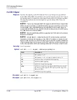
Set DS1 Type
Purpose:
Sets DS1 type. The Access Navigator allows the user to assign any DS1 for drop,
groom, or switch operation. If the DS1 type is switch, be sure that the switch type is
also defined (see “Set Switch Type” on page 18-131).
NOTE:
The default for DCS systems sets all DS1s to drop. The default for
GR-303 systems sets DS1s 1-24 to drop and DS1s 25-32 to switch.
NOTE:
If the DS1 is part of a fractional interface used to provision a remote
Access Bank II, the DS1 type can not be changed without first deleting the
fractional interface. (
Provision Remote Access Bank II
on
page 11-1
)
Security:
Level 2 (operator)
Syntax:
set ds1 <n> type
<
drop
|
groom
|
switch
>
Example:
set ds1 1-18 type drop
Example:
set ds1 25-32 type switch
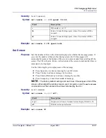
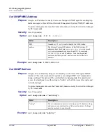
Set EOC
Purpose:
Sets the location of the primary and secondary EOCs on “switch” DS1s. GR-303 switch
DS1s carry an Embedded Operations Channel (EOC) and Timeslot Management
Channel (TMC) for call control. Primary and secondary EOC and TMC lines provide
protection.
NOTE:
For proper operation, the first switch DS1 (TermID = 1) in the GR-
303 interface group must contain the primary EOC and TMC. The second DS1
(TermID = 2) must contain the secondary EOC and TMC. By default, DS1 #25
is TermID 1 and DS1 #29 is TermID 2.
NOTE:
It is recommended that primary and secondary EOC and TMC be
assigned to different Quad T1 Framer (QF) cards for added protection. In the
event one QF card fails, the GR-303 switch will then be able to continue service
using the redundant EOC and TMC on a different QF card. QF card #1 contains
DS1 #1 to #4 contains DS1 #5 to #8, etc. By default, the primary EOC and TMC
are on DS1 #25 and the secondary EOC and TMC are on DS1 #29.
NOTE:
A minor alarm will occur if the EOC is set to None.
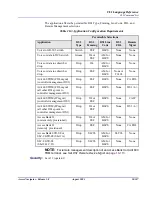
Field
Description
n
DS1 number, 1 to 32, or a range of numbers such as 2-8.
drop
DS1s terminated at a remote terminal.
groom
DS1s terminated at a DCS or Frame Relay.
switch
DS1s terminated at the IDT (GR-303 switch).
Содержание Access Navigator
Страница 1: ...Access Navigator USER MANUAL Part Number 770 0079 AP Product Release 1 8 August 2003 ...
Страница 82: ...4 18 August 2003 Access Navigator Release 1 8 Access Navigator GR 303 Host with P Phone Ordering Information ...
Страница 104: ...5 22 August 2003 Access Navigator Release 1 8 Physical Installation Attach Access Navigator to Plywood ...
Страница 170: ...6 66 August 2003 Access Navigator Release 1 8 Electrical Installation Exit Management Session ...
Страница 182: ...7 12 August 2003 Access Navigator Release 1 8 Start Management Session NetworkValet EMS and Valet Management ...
Страница 214: ...9 20 August 2003 Access Navigator Release 1 8 Provision DCS Service Test DS1 and DS0 Circuits ...
Страница 296: ...12 18 August 2003 Access Navigator Release 1 8 Provision Remote Adit 600 via FDL Test DS1 and DS0 Circuits ...
Страница 320: ...13 24 August 2003 Access Navigator Release 1 8 Provision Remote Adit 600 via IP DS0 Test DS1 and DS0 Circuits ...
Страница 342: ...14 22 August 2003 Access Navigator Release 1 8 Alarm Clearing Ethernet Link Status LED ...
Страница 434: ...16 36 August 2003 Access Navigator Release 1 8 Maintenance Procedures Install SIMM on Controller Card ...
Страница 456: ...17 22 August 2003 Access Navigator Release 1 8 Update Controller Card Software Download Software ...
Страница 634: ...18 178 August 2003 Access Navigator Release 1 8 CLI Language Reference CLI Command List ...
Страница 658: ...B 6 August 2003 Access Navigator Release 1 8 FDL Interface Access Bank II Capabilities ...
Страница 668: ...C 10 August 2003 Access Navigator Release 1 8 SNMP Interface SNMP Trap Reports ...
Страница 682: ...GlossaryGlossaryGlossaryGlossary 14 August 2003 Access Navigator Release 1 8 Glossary ...
Страница 704: ...Index 1 22 August 2003 Access Navigator Release 1 8 Index ...


