S T E P 9
S T E P 9 – C o n t r o l l e r
68
docs.carbide3d.com
69
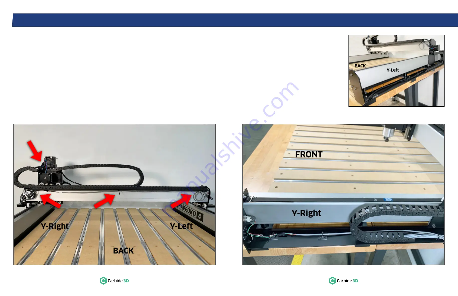
9.6 Connect Cables
1. Connect the X- and Z-motor cables and the
Z-proximity switch connectors at the back of
the X/Z assembly.
See
Fig. 9-6
.
a. Z-motor is the top motor.
b. Z-proximity switch has a 3-pin connector.
2. Connect the X-, Y-Right, and Z-motor
extension cables, and the X- and Z-proximity
switches at the Y-Right carriage.
See
Fig. 9-6
.
Figure 9-6
Figure 9-7
Figure 9-8
3. Extend the Y-Left stepper motor extension
cable across the back of the gantry to the
Y-Right carriage.
4. Connect of the Y-Left motor extension cable to
the corresponding cable at Y-Right.
PRO TIP:
After connecting all labeled cables, any
unlabeled cables can be matched according to
connector type.
9.7 Tidy Cables
1. Use a few zip ties to secure loose cables
(see
Figs. 9-6, 9-7,
and
9-8)
:
a. At the back of the X/Z assembly.
b. Extending along the back of the X-Axis
gantry to the underside of the X-Axis drag
chain support panel.
c. Entering the controller.
d. Power button wiring along Y-Right.
e. Router power cable along Y-Left.
Содержание Shapeoko 4 XXL
Страница 1: ...Shapeoko 4 XXL ASSEMBLY GUIDE...


