S T E P 9
S T E P 9 – C o n t r o l l e r
66
docs.carbide3d.com
67
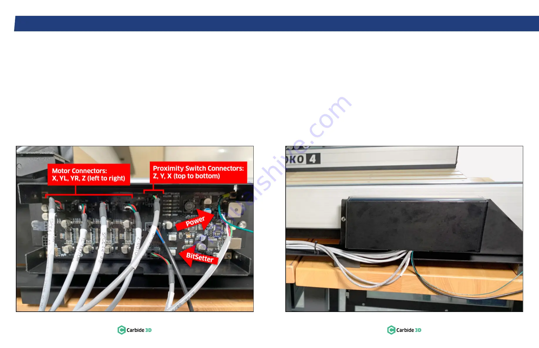
9.5 Connect Controller Cables
1. Plug the gray 4-pin male power extension
cable into the 4-pin female connector at the
top-right of the controller labeled “Pwr_conn”.
See
Fig. 9-4
.
2. If you have purchased the optional BitSetter
accessory, plug the 3-pin female BitSetter
cable into the 3-pin male connector at the
bottom of the controller labeled “BitSetter”.
See
Fig. 9-4
.
Figure 9-4
Figure 9-5
3. Plug the three 8-pin male proximity switch
cables into the 8-pin female connectors down
the center of the controller labeled “Z”, “Y”,
“X”.
See
Fig. 9-4
.
4. Plug the four 4-pin male stepper motor cables
into the 4-pin female connectors at the top-left
labeled “X”, “Y2”, “Y1”, “Z”.
See
Fig. 9-4
.
a. Y-RIGHT motor cable into “Y1” connector.
b. Y-LEFT motor cable into “Y2” connector.
PRO TIP:
Keep an eye on the gantry when you
home the machine for the first time. The gantry
should home to the back-right corner. If your
gantry moves forward during homing, you may
need to swap the Y-Left and Y-Right motor cables
at the controller.
5. Use the four (4) thumbscrews to attach the
controller cover.
See
Fig. 9-5
.
a. Direct all of the cables into the notch at the
bottom.
Содержание Shapeoko 4 XXL
Страница 1: ...Shapeoko 4 XXL ASSEMBLY GUIDE...


