24
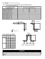
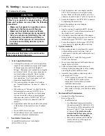
- The wall is 12” thick or less
- An air space of at least of that shown
in Figure 8 is maintained around
outside of the vent pipe to provide air
circulation
• If above three conditions cannot be
met simultaneously when penetrating
a combustible wall, use a single wall
thimble [Burnham Commercial part
numbers 102181-01 (4”) and 103419-01
(6”)].
• Thimble use is optional for non-
combustible wall.
• Insert thimble into cut opening from
outside. Secure thimble outside flange to
wall with nails or screws and seal ID and
OD with sealant material.
• When thimble is not used for non-
combustible wall, size and cut wall opening
such that a minimal clearance is obtained
and to allow easy insertion of vent pipe.
• Apply sealant between vent pipe and
thimble or wall opening to provide weather-
tight seal. Sealant should not restrain the
expansion of the vent pipe.
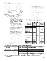
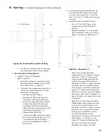
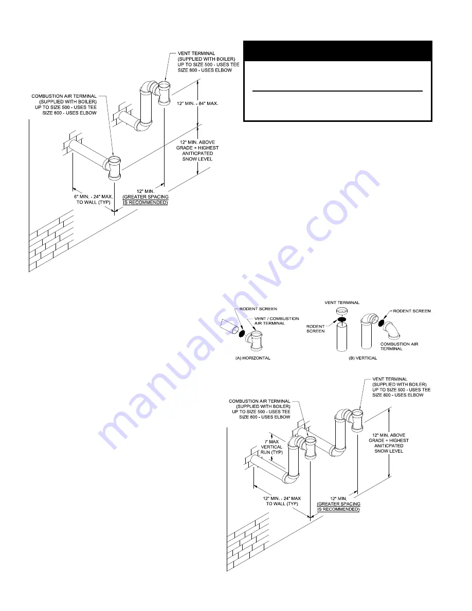
• Install Rodent Screen and Vent Terminal
(supplied with boiler). See Figure 10 for
appropriate configuration details.
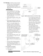
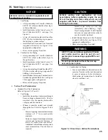
Figure 10: rodent Screen installation
iV. Venting
B. CPVC/PVC Venting (continued)
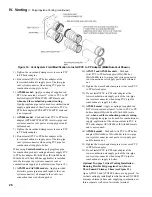
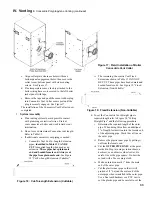
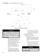
Figure 9B: Direct Vent - Sidewall Terminations (Optional)
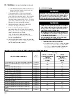
Warning
all CPVC pipe supplied with boiler vent carton
must be used as part of vent system prior to
connecting supplied PVC vent terminal.
Methods of securing and sealing terminals to
the outside wall must not restrain the thermal
expansion of the vent pipe.
ii
. Combustion Air Piping
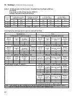
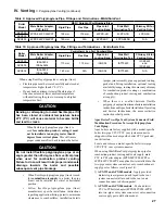
• Do not exceed maximum combustion air
pipe length. Refer to Table 8.
• Size combustion air pipe wall penetration
opening to allow easy insertion of the pipe.
• Install Rodent Screen and Combustion Air
Terminal (supplied with boiler). See Figure
10 for appropriate configuration details.
• Apply sealant between combustion air pipe
and wall opening to provide weather-tight
seal.
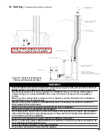
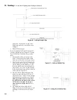
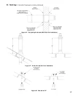
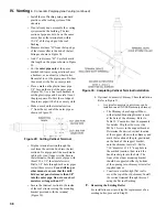
b. Optional Two-Pipe Snorkel Termination
See Figures 10 and 11.
This installation will allow a maximum of seven (7)
feet vertical exterior run of the vent/combustion air
piping to be installed on the CPVC/PVC horizontal
venting application.
Figure 11: Direct Vent - Optional Sidewall
Snorkel Terminations
Содержание Apex APX399
Страница 7: ...7 I Product Description Specifications and Dimensional Data continued Figure 1A Apex Model APX399 ...
Страница 8: ...8 Figure 1B Apex Model APX500 I Product Description Specifications and Dimensional Data continued ...
Страница 9: ...9 I Product Description Specifications and Dimensional Data continued Figure 1C Apex Model APX800 ...
Страница 65: ...65 VIII Electrical continued Figure 43 Ladder Diagram ...
Страница 66: ...66 VIII Electrical continued ...
Страница 67: ...67 Figure 44 Wiring Connections Diagram VIII Electrical continued ...
Страница 110: ...110 1P 3 1P 2 1P 1 XIII Repair Parts continued 1C 1D 1E ...
Страница 116: ...116 XIII Repair Parts continued ...
Страница 118: ...118 XIII Repair Parts continued ...
Страница 129: ...129 SERVICE RECORD DATE SERVICE PERFORMED ...
Страница 130: ...130 SERVICE RECORD DATE SERVICE PERFORMED ...
Страница 131: ...131 SERVICE RECORD DATE SERVICE PERFORMED ...


