


21
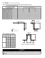
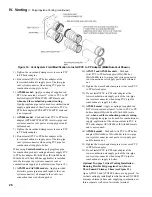
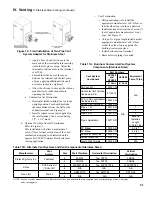
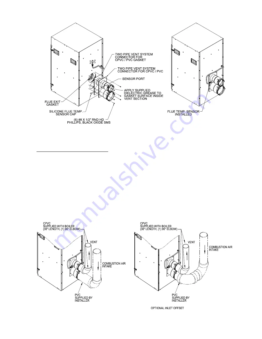
Figure 6: Field installation of CPVC/PVC Two-Pipe Vent System Connector
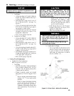
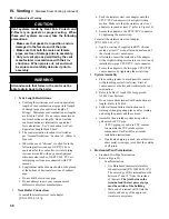
iV. Venting
B. CPVC/PVC Venting (continued)
4.
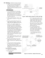
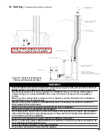
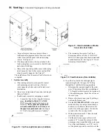
Near-Boiler Vent/Combustion Air Piping
Refer to Figure 7 and the following Steps:
APX399 and APX500 Boiler Models:
a. 4” x 4” Two-Pipe CPVC/PVC Vent System
Connector (P/N 102183-03), used on APX399
and APX500 boiler models, has factory installed
internal sealing gaskets at both vent and air
intake sections.
b. Install provided 4” Schedule 40 x 30” long
CPVC pipe into the connector vent section with
a slight twisting motion and secure by tightening
the metal strap.
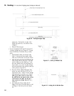
c. All CPVC vent components supplied with
boiler inside vent carton (4” Schedule 40 x 30”
Figure 7: near-Boiler Vent/Combustion air Piping
long CPVC pipe and 4” Schedule 80 CPVC
90° Elbow) must be used for near-boiler piping
before transitioning to Schedule 40 PVC (ASTM
2665) pipe components for reminder of vent
system. The CPVC 30” long straight pipe may be
cut to accommodate desired vent configuration
provided both pieces are used in conjunction
with CPVC 90° Elbow before any PVC
components are used. Ensure that the CPVC 90°
Elbow is the first elbow used in the vent system
as it exits the boiler.
d. Insert 4” Schedule 40 PVC combustion air pipe
(installer provided) into the connector air intake
section with a slight twisting motion and secure
by tightening the metal strap.
Содержание Apex APX399
Страница 7: ...7 I Product Description Specifications and Dimensional Data continued Figure 1A Apex Model APX399 ...
Страница 8: ...8 Figure 1B Apex Model APX500 I Product Description Specifications and Dimensional Data continued ...
Страница 9: ...9 I Product Description Specifications and Dimensional Data continued Figure 1C Apex Model APX800 ...
Страница 65: ...65 VIII Electrical continued Figure 43 Ladder Diagram ...
Страница 66: ...66 VIII Electrical continued ...
Страница 67: ...67 Figure 44 Wiring Connections Diagram VIII Electrical continued ...
Страница 110: ...110 1P 3 1P 2 1P 1 XIII Repair Parts continued 1C 1D 1E ...
Страница 116: ...116 XIII Repair Parts continued ...
Страница 118: ...118 XIII Repair Parts continued ...
Страница 129: ...129 SERVICE RECORD DATE SERVICE PERFORMED ...
Страница 130: ...130 SERVICE RECORD DATE SERVICE PERFORMED ...
Страница 131: ...131 SERVICE RECORD DATE SERVICE PERFORMED ...


