79
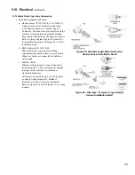
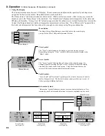
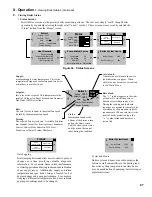
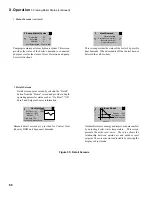
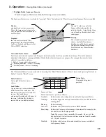
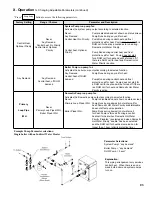
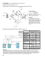
Figure 53: Dungs gas Valve Detail
Table 25: number of Clockwise Throttle Screw
Turns for LP Conversion
Boiler
Model
gas Valve
Throttle Screw Turns at
altitude range
0 - 7000 Ft.
APX399
Dungs
GB-057 HO
(¾” NPT)
1¾
APX500
Dungs
GB-057 HO
(¾” NPT)
1
APX800
Dungs GB-ND057
D01 S00 XP
(¾” NPT)
N/A
See Tables 2A & 2B
Notes
iX. System Start-up
(continued)
N.
Test External Limits
Test any external limits or other controls in accordance
with the manufacturer’s instructions.
O.
Check Thermostat Operation
Verify that the boiler starts and stops in response to
calls for heat from the heating thermostat and indirect
water heater thermostat. Make sure that the appropriate
circulators also start and stop in response to the
thermostats.
P.
Adjust Supply Water Temperature
As shipped, the heating set point supply temperature is
set to 180°F and, indirect water heater set point supply
temperature is set to 170°F. If necessary, adjust these to
the appropriate settings for the type of system to which
this boiler is connected. See Section X “Operation”
(parameter Table on page 97) of this manual for
information on how to do this.
Q.
Adjust Thermostats
Adjust the heating and indirect water heater thermostats
to their final set points.
R.
Field Conversion From Natural Gas to LP Gas
Apex boiler models APX399 and APX500 are factory
shipped as Natural Gas builds and can be field
converted to LP gas. Follow steps below for field
conversion from Natural Gas to LP Gas.
Boiler model APX800 is factory shipped as either
Natural Gas build or LP Gas build. Field conversions of
model APX800 are not permitted.
1. Conversion of Apex models APX399 and APX500
from one fuel to another is accomplished using the
throttle screw on the gas valve. Figure 53 “Dungs
Gas Valve Detail” shows the location of the throttle
screw on the Dungs valve. Locate the throttle screw
on the boiler being converted.
Warning
This conversion should be performed by a
qualified service agency in accordance with the
manufacturer’s instructions and all applicable
codes and requirements of the authority
having jurisdiction. if the information in these
instructions is not followed exactly, a fire, an
explosion or production of carbon monoxide
may result causing property damage, personal
injury, or loss of life. The qualified service
agency is responsible for proper conversion of
these boilers. The conversion is not proper and
complete until the operation of the converted
appliance is checked as specified in this manual.
2. If conversion is being made on a new installation,
install the boiler in accordance with the installation
instructions supplied with the boiler. If an installed
boiler is being converted, connect the new gas
supply to the boiler, check for gas leaks, and purge
the gas line up to the boiler in accordance with
the National Fuel Gas Code (ANSI Z223.1) or the
requirements of the authority having jurisdiction.
3. Before attempting to start the boiler, make the
number of turns to the throttle screw called for in
Table 25.
4. Attempt to start the boiler using the lighting instructions
located inside the lower front cover of the boiler. If the
boiler does not light on the first try for ignition, allow
to boiler to make at least four more attempts to light.
If boiler still does not light, turn the throttle counter
clockwise in 1/4 turn increments, allowing the boiler
to make at least three tries for ignition at each setting,
until the boiler lights.
5.
After the burner lights, force the burner to high fire.
Allow the boiler to operate for approximately 5 minutes
before taking combustion readings.
6. Check/adjust rate (see Paragraph L), then perform a
combustion test (see Paragraph M).
Warning
The throttle adjustments shown in Table 25 are
approximate. The final throttle setting must be
found using a combustion analyzer. Leaving the
boiler in operation with a CO level in excess of
the value shown in Table 26 could result in injury
or death from carbon monoxide poisoning.
Содержание Apex APX399
Страница 7: ...7 I Product Description Specifications and Dimensional Data continued Figure 1A Apex Model APX399 ...
Страница 8: ...8 Figure 1B Apex Model APX500 I Product Description Specifications and Dimensional Data continued ...
Страница 9: ...9 I Product Description Specifications and Dimensional Data continued Figure 1C Apex Model APX800 ...
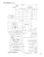
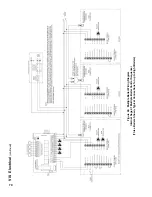
Страница 65: ...65 VIII Electrical continued Figure 43 Ladder Diagram ...
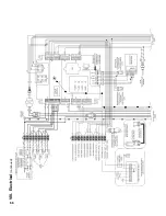
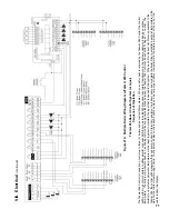
Страница 66: ...66 VIII Electrical continued ...
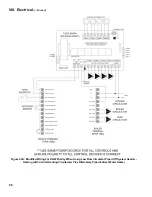
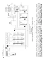
Страница 67: ...67 Figure 44 Wiring Connections Diagram VIII Electrical continued ...
Страница 110: ...110 1P 3 1P 2 1P 1 XIII Repair Parts continued 1C 1D 1E ...
Страница 116: ...116 XIII Repair Parts continued ...
Страница 118: ...118 XIII Repair Parts continued ...
Страница 129: ...129 SERVICE RECORD DATE SERVICE PERFORMED ...
Страница 130: ...130 SERVICE RECORD DATE SERVICE PERFORMED ...
Страница 131: ...131 SERVICE RECORD DATE SERVICE PERFORMED ...

