

61
4. All above ground gas piping upstream from manual
shut-off valve must be electrically continuous and
bonded to a grounding electrode. Do not use gas
piping as grounding electrode. Refer to
National
Electrical Code
, NFPA 70.
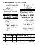
C.
Pressure test.
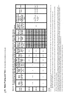
See Table 22 for Apex Min./Max.
Pressure Ratings. The boiler and its gas connection
must be leak tested before placing boiler in operation.
1. Protect boiler gas control valve. For all testing over
½ psig, boiler and its individual shutoff valve must
be disconnected from gas supply piping. For testing
at ½ psig or less, isolate boiler from gas supply
piping by closing boiler’s individual manual shutoff
valve.
2. Locate leaks using approved combustible gas non-
corrosive leak detector solution.
Table 21: Specific Gravity Correction Factors
Specific
gravity
Correction
Factor
Specific
gravity
Correction
Factor
0.60
1.00
0.90
0.82
0.65
0.96
1.00
0.78
0.70
0.93
1.10
0.74
0.75
0.90
1.20
0.71
0.80
0.87
1.30
0.68
0.85
0.81
1.40
0.66
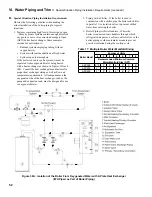
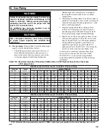
1. Use methods and materials in accordance with local
plumbing codes and requirements of gas supplier. In
absence of such requirements, follow
National Fuel
Gas Code
, NFPA 54/ANSI Z223.1.
2. Use thread (joint) compounds (pipe dope) resistant
to action of liquefied petroleum gas.
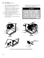
3. Apex (APX) boilers have factory supplied
Miscellaneous Part Cartons (P/N 102942-03 –
APX500, or, P/N 103259-01 – APX800), which
include gas-piping components to connect boiler
gas valve(s) to gas supply system. Install these
components prior to connecting boiler to gas supply
system piping as follows:
APX500
a. Locate and remove the ¾” NPT x 6” long black
nipple and ¾” NPT external gas shutoff valve
(required for APX500).
b. APX500 boiler has ¾” NPT x 12” long black
nipple and left side panel grommet factory
installed (disregard the supplied ¾” NPT x 6”
long black nipple in the Miscellaneous Part
Carton).
c. Mount the ¾” NPT external gas shutoff valve
onto the nipple threaded end outside of the jacket
left side panel.
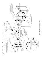
d. Install sediment trap, ground-joint union and
manual shut-off valve upstream of mounted
factory supplied manual shut-off valve. See
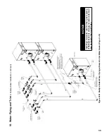
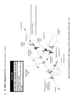
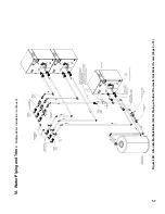
Figure 41 “ Recommended Gas Piping ”.
APX800
e. Locate and remove 1” NPT external gas shutoff
valve.
f. APX800 boiler has 1” NPT x 3” long black
nipple and left side panel grommet factory
installed.
g. Mount the 1” NPT external gas shutoff valve
onto the nipple threaded end outside of the jacket
left side panel.
h. Install sediment trap, ground-joint union and
manual shut-off valve upstream of mounted
factory supplied manual shut-off valve. See
Figure 41 “ Recommended Gas Piping”.
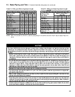
Vii. gas Piping
(continued)
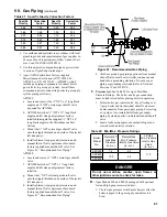
Boiler
Model
No.
Natural/LP
Gas Max.
Pressure
(in. w.c.)
Natural Gas
Min. Pressure
Inlet to Gas Valve
(in. w.c.)
LP Gas
Min. Pressure
Inlet to Gas
Valve
(in. w.c.)
APX399
14
4,0
11.0
APX500
13.5
4.5
APX800
Table 22: Min./Max. Pressure ratings
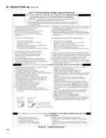
Figure 41: recommended gas Piping
DangEr
Do not use matches, candles, open flames or
other ignition source to check for leaks.
D.
Apex Models 500 and 800 (if equipped with optional
low and high gas pressure switches):
1. The low gas pressure switch must be reset after the
boiler is piped to the gas supply and before it is
fired.
Содержание Apex APX399
Страница 7: ...7 I Product Description Specifications and Dimensional Data continued Figure 1A Apex Model APX399 ...
Страница 8: ...8 Figure 1B Apex Model APX500 I Product Description Specifications and Dimensional Data continued ...
Страница 9: ...9 I Product Description Specifications and Dimensional Data continued Figure 1C Apex Model APX800 ...
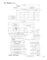
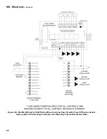
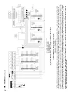
Страница 65: ...65 VIII Electrical continued Figure 43 Ladder Diagram ...
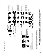
Страница 66: ...66 VIII Electrical continued ...
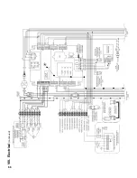
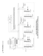
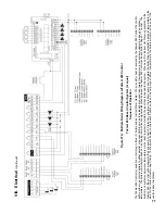
Страница 67: ...67 Figure 44 Wiring Connections Diagram VIII Electrical continued ...
Страница 110: ...110 1P 3 1P 2 1P 1 XIII Repair Parts continued 1C 1D 1E ...
Страница 116: ...116 XIII Repair Parts continued ...
Страница 118: ...118 XIII Repair Parts continued ...
Страница 129: ...129 SERVICE RECORD DATE SERVICE PERFORMED ...
Страница 130: ...130 SERVICE RECORD DATE SERVICE PERFORMED ...
Страница 131: ...131 SERVICE RECORD DATE SERVICE PERFORMED ...


