


30
iV. Venting
D. Stainless Steel Venting (continued)
D.
Stainless Steel Venting
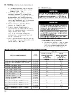
CaUTiOn
Vent systems made by Heat Fab, Protech and
Z-Flex rely on gaskets or proper sealing. When
these vent systems are used, take the following
precautions:
• Make sure that gasket is in position and un-
damaged in the female end of the pipe.
• Make sure that both the male and female
pipes are free of damage prior to assembly.
• Only cut vent pipe as permitted by the vent
manufacturer in accordance with their in-
structions. When pipe is cut, cut end must
be square and carefully de-burred prior to
assembly.
Warning
all condensate that forms in the vent must be
able to drain back to the boiler.
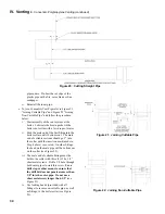
1.
Vent Length Restrictions
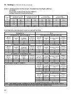
a. Vent length restrictions are based on equivalent
length of vent/combustion air pipe (total length
of straight pipe plus equivalent length of
fittings). Maximum vent/combustion air lengths
are listed in Table 8. Do not exceed maximum
vent/combustion air lengths. Do not include
vent/combustion air terminals in equivalent
feet calculations. See “Combustion Air/Vent,
Equivalent Length Work Sheet”.
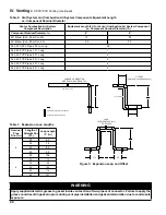
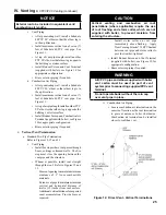
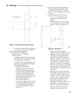
b. The vent termination location is restricted as
per ‘General Guidelines’, Section A.5. (Refer to
Figure 4)
c. Where the use of “silicone” is called for in the
following instructions, use GE RTV 106 or
equivalent for the vent collar. Air inlet piping
sections are sealed with any general-purpose
silicone sealant such as GE RTV102. PVC air
inlet piping sections are connected with PVC
cement.
d. Longitudinal welded seams should not be placed
at the bottom of horizontal sections of exhaust
pipe.
e. Do not drill holes in vent pipe.
f. Do not attempt to mix vent components of
different vent system manufacturers.
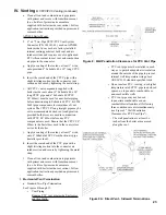
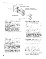
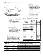
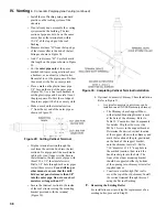
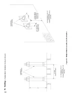
2.
Near Boiler Connection
To install the stainless steel vent adapter
[P/N 102220-01 (4”)]:
a. Push the stainless steel vent adapter onto the
CPVC/PVC connector with a slight twisting
motion. Make sure that the stainless steel vent
adapter is inserted at least 1” (refer to Figure 16).
b. Secure the adapter to the CPVC/PVC connector
by tightening the metal strap.
To install the stainless steel vent adapter
[P/N 103285-01 (6”)]:
c. Apply a coating of supplied red RTV silicone
sealant, at least 1” wide, all around male end of
the stainless steel vent adapter.
d. Afterwards, insert the male end of the adapter
with a slight twisting motion into vent section of
installed two-pipe CPVC/PVC vent connector.
e. Secure the adapter to the two-pipe CPVC/PVC
vent connector by tightening the metal strap.
3.
System Assembly
a. Plan venting system to avoid possible contact
with plumbing or electrical wires. Start at
vent connector at boiler and work towards vent
termination.
b. Refer to Tables 11A and 11B for approved
AL29C Vent Systems.
c. Do not exceed maximum Vent/Combustion air
length. Refer to Table 8.
d. Follow all manufacturer instructions and
warnings when preparing pipe ends for joining
and using the primer and the cement.
e. Assemble the air intake system using either
galvanized or PVC pipe.
i.
If PVC piping is used, use PVC cement
to assemble the PVC intake system
components. See Part B for air intake
installation instructions.
ii.
If galvanized piping is used, use at least two
sheet metal screws per joint. Seal the outside
of all joints.
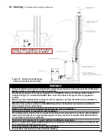
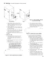
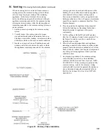
4.
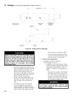
Horizontal Vent Termination
a. Standard Two-Pipe Termination
Refer to Figure 9A.
i.
Vent Termination
• Use Burnham Commercial stainless
exhaust terminal [P/N 100184-01 (4”)].
The outer edge of this terminal must be
between 6” and 12” from the surface
of the wall.
The joint between the
terminal and the last piece of pipe
must be outside of the building
.
• Male end of terminal will fit into the
female end of any of the approved
stainless vent systems.
Содержание Apex APX399
Страница 7: ...7 I Product Description Specifications and Dimensional Data continued Figure 1A Apex Model APX399 ...
Страница 8: ...8 Figure 1B Apex Model APX500 I Product Description Specifications and Dimensional Data continued ...
Страница 9: ...9 I Product Description Specifications and Dimensional Data continued Figure 1C Apex Model APX800 ...
Страница 65: ...65 VIII Electrical continued Figure 43 Ladder Diagram ...
Страница 66: ...66 VIII Electrical continued ...
Страница 67: ...67 Figure 44 Wiring Connections Diagram VIII Electrical continued ...
Страница 110: ...110 1P 3 1P 2 1P 1 XIII Repair Parts continued 1C 1D 1E ...
Страница 116: ...116 XIII Repair Parts continued ...
Страница 118: ...118 XIII Repair Parts continued ...
Страница 129: ...129 SERVICE RECORD DATE SERVICE PERFORMED ...
Страница 130: ...130 SERVICE RECORD DATE SERVICE PERFORMED ...
Страница 131: ...131 SERVICE RECORD DATE SERVICE PERFORMED ...


