


104
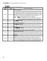
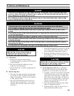
Xi. Service and Maintenance
(continued)
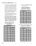
Outdoor Temperature
Ohms of
resistance
°F
°C
-20
-28.9
106926
-10
-23.3
80485
0
-17.8
61246
10
-12.2
47092
20
-6.7
36519
30
-1.1
28558
40
4.4
22537
50
10.0
17926
60
15.6
14356
70
21.1
11578
76
24.4
10210
78
25.6
9795
80
26.7
9398
90
32.2
7672
100
37.8
6301
110
43.3
5203
120
48.9
4317
Outdoor air Temperature Sensor
Temperature versus resistance
(P/n 102946-01)
(10kOhm nTC Sensor)
Temperature
Ohms of
resistance
°F
°C
32
0
36100
50
10
22790
68
20
14770
77
25
12000
86
30
9810
104
40
6653
122
50
4610
140
60
3250
158
70
2340
176
80
1710
194
90
1270
212
100
950
230
110
730
248
120
560
Supply, return and Stack Temperature Sensor
Temperature versus resistance
(12kOhm nTC Sensor), Beta of 3750
Header Temperature Sensor
Temperature versus resistance
(P/n 101935-01 or 103104-01)
(10kOhm nTC Sensor), Beta of 3950
Temperature
Ohms of
resistance
°F
°C
32
0
32648
50
10
19898
68
20
12492
77
25
10000
86
30
8057
104
40
5327
122
50
3602
140
60
2488
158
70
1752
176
80
1256
194
90
916
212
100
697
248
120
386
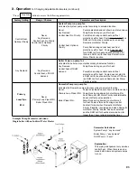
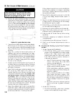
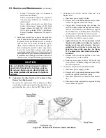
e. Using pliers, release spring clip securing the
overflow switch to condensate trap body and remove
the switch. Note that the switch has factory applied
silicon adhesive seal, which may have to be carefully
cut all around to facilitate the switch removal.
f. Using pliers, release spring clip securing condensate
trap body to the heat exchanger bottom drain stab.
g. Firstly, pull the trap downwards to release from
the heat exchanger bottom drain stab; secondly,
pull the trap end from left side jacket panel sealing
grommet and remove the trap from boiler.
h. To reinstall the trap, reverse above steps.
i. If the original condensate overflow switch is to
be re-used, follow the appropriate switch removal
steps from Condensate Overflow Switch Removal
and Replacement procedure above.
j.
Insure that fresh silicon sealant is applied to
the overflow switch threads, and the switch is
properly oriented relative to the trap body -
the arrow molded into the switch hex side end
must face down for proper switch operation.
See Figure 59 “Condensate Overflow Switch
Orientation” for details. Insure that pressure
switch hose is reconnected to the trap.
k. Restore power supply to boiler. Fill up the trap
(see Section V “Condensate Disposal”) and
verify the switch operation.
Содержание Apex APX399
Страница 7: ...7 I Product Description Specifications and Dimensional Data continued Figure 1A Apex Model APX399 ...
Страница 8: ...8 Figure 1B Apex Model APX500 I Product Description Specifications and Dimensional Data continued ...
Страница 9: ...9 I Product Description Specifications and Dimensional Data continued Figure 1C Apex Model APX800 ...
Страница 65: ...65 VIII Electrical continued Figure 43 Ladder Diagram ...
Страница 66: ...66 VIII Electrical continued ...
Страница 67: ...67 Figure 44 Wiring Connections Diagram VIII Electrical continued ...
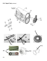
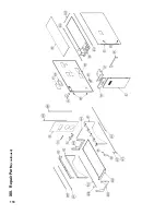
Страница 110: ...110 1P 3 1P 2 1P 1 XIII Repair Parts continued 1C 1D 1E ...
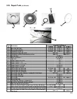
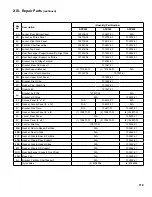
Страница 116: ...116 XIII Repair Parts continued ...
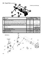
Страница 118: ...118 XIII Repair Parts continued ...
Страница 129: ...129 SERVICE RECORD DATE SERVICE PERFORMED ...
Страница 130: ...130 SERVICE RECORD DATE SERVICE PERFORMED ...
Страница 131: ...131 SERVICE RECORD DATE SERVICE PERFORMED ...


