


106
Xii. Troubleshooting
(continued)
indication
Condition
Possible Cause
Sequencer
Setup
Flashing
Sequencer
Setup
Fault
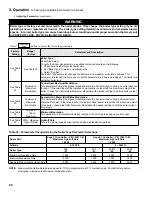
This alarm is active if the slave boiler has lost communication with the Sequence Master. Check
the following:
- RJ 45 peer-to-peer network disconnected
- Sequencer Master was Enabled and then Disabled
- Master’s Boiler has been powered down.
- To clear fault restore communication or cycle power
Boiler Size
Setup
Flashing
Boiler
Size
Fault
Warning!
Boiler size setting may not match actual boiler size.
The Boiler size setting determines min, max and light-off blower speeds. Incorrect boiler size can
cause hazardous burner conditions and improper operation that may result in PROPERTY LOSS,
PHYSICAL INJURY, OR DEATH.
Refer to Page 92 for boiler size setting instructions.
C.
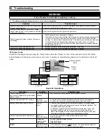
Help Screen Faults
D.
Help Screen Diagnostic Features
indication
Possible Cause
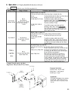
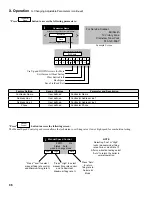
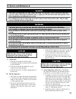
Lockout History is stored in a first-in, first-out basis. Each History file is stored with boiler run hour of when the
lockout occurred.
The “When happened” and “Current” provide:
- “Current” is the run hour and status the boiler just finished.
- “When happened” is the run hour and status when the lockout occurred.
For Service Contact:
CONTRACTOR NAME
CONTRACTOR ADDRESS
1
CONTRACTOR ADDRESS
2
PHONE NUMBER
The user is given the contact information of the responsible service provider. Refer to page 96 for data entry
instructions.
Supply High Limit
Lockout History 1 of 10 (newest)
<
>
i
Status
Run Time Hour
Running
Lockout
50
50
When happened Current
indication
Condition
Possible Cause
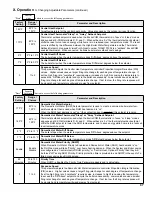
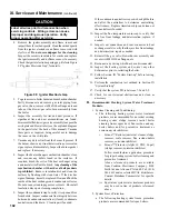
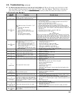
Limit String Status
Air
Press
Switch
Limit String Status
i
Auto
Reset
Hi Limit
Condensate
Float Switch
(&
Thermal Link
on Size > 210)
(
Gas Press Switch
,
LWCO,
External Hi Limit
When provided
)
Limit String
Fault
The Limit String Status screen shows the faulty safety limit. A contact icon, either “open” or
“closed”, graphically represents each safety limit. The “closed” contact icon is steady; the “open”
contact icon is blinking. For example, the screen shown to the left illustrates a “closed” Air
Pressure Switch contact and an “open’ Auto Reset High Limit contact. The Auto Reset High Limit
is causing the boiler to stop firing.
NOTE: Since the limit string items are wired in series, all limits downstream of the “open” limit will
also appear on the screen as “open” (blinking) icons regardless of whether or not they are actually
open.
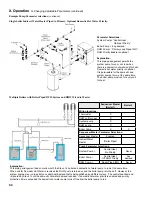
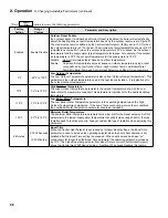
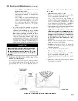
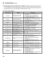
Sensor Status
i
Supply Sensor 180 F Normal
Return Sensor
768
F Shorted
Stack Sensor
024
F Open
Outdoor Sensor 45 F Normal
Header Sensor None
4-20mA Input 4 mA Normal
Sensor
Fault
The Sensor Status screen shows the status of all sensors. Possible states include:
None:
Feature requiring this sensor has not been selected.
Normal: Sensor is working normally.
Shorted: Sensor is shorted or is defective.
Open:
There is a break in the wiring between the Control and the sensor or the sensor is
defective
Out of Range: Sensor is defective or is being subjected to electrical noise.
Unreliable: Sensor is defective or is being subjected to electrical noise.
When a sensor fails “opened” or “shorted” the value is changed to reverse video (background
black and value white) “024” or “768” respectively to indicate that there is a fault with the sensor.
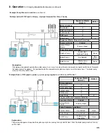
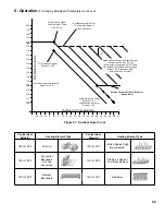
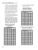
Rate Limit
i
Active Rate Limiter
:
Rate Limits
High Stack Temp Rate Limit
Active Rate Override
:
Burner Control Rate Override
High Stack
Temperature
Rate Limit
The following messages appear when the firing rate is limited or reduced to help avoid a lockout.
Refer to lockout section for potential corrective action.
- High Stack Temperature Limit
- High Supply Temperature Limit
- High Differential Temperature Limit
The following messages appear as part of a normal start and stop sequence:
- Minimum Modulate (normal start/stop sequence)
- Forced Modulation (normal start/stop sequence)
- Burner Control Rate (normal start/stop sequence)
- Manual Firing Rate ( User selection)
E.
Active Fault Screen Faults
Содержание Apex APX399
Страница 7: ...7 I Product Description Specifications and Dimensional Data continued Figure 1A Apex Model APX399 ...
Страница 8: ...8 Figure 1B Apex Model APX500 I Product Description Specifications and Dimensional Data continued ...
Страница 9: ...9 I Product Description Specifications and Dimensional Data continued Figure 1C Apex Model APX800 ...
Страница 65: ...65 VIII Electrical continued Figure 43 Ladder Diagram ...
Страница 66: ...66 VIII Electrical continued ...
Страница 67: ...67 Figure 44 Wiring Connections Diagram VIII Electrical continued ...
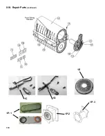
Страница 110: ...110 1P 3 1P 2 1P 1 XIII Repair Parts continued 1C 1D 1E ...
Страница 116: ...116 XIII Repair Parts continued ...
Страница 118: ...118 XIII Repair Parts continued ...
Страница 129: ...129 SERVICE RECORD DATE SERVICE PERFORMED ...
Страница 130: ...130 SERVICE RECORD DATE SERVICE PERFORMED ...
Страница 131: ...131 SERVICE RECORD DATE SERVICE PERFORMED ...


