Installation and Operating Manual
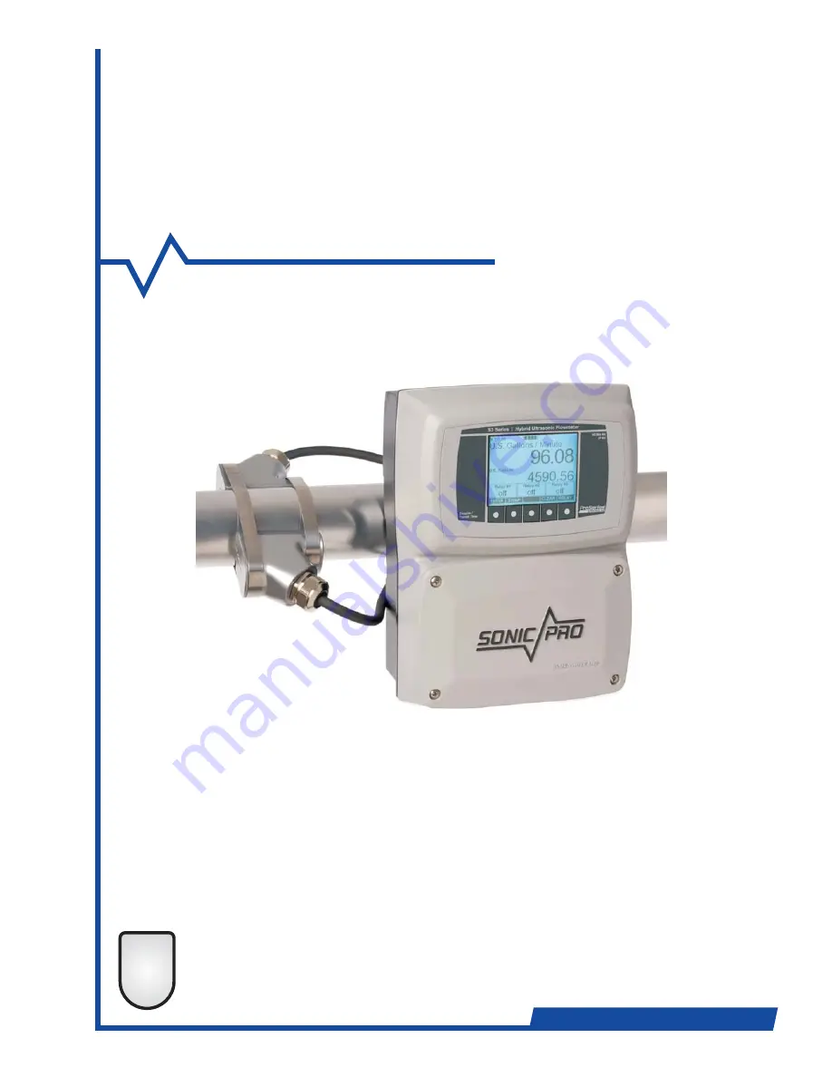
Hybrid Ultrasonic Flowmeter
SONIC-PRO
Industries, Ltd.
ProSeries
by Blue-White Ind.
TM
2
TWO-YEAR
WARRANTY
Страница 1: ...Installation and Operating Manual HybridUltrasonicFlowmeter SONIC PRO Industries Ltd Industries Ltd ProSeries by Blue White Ind TM 2 TWO YEAR WARRANTY ProSeries...
Страница 2: ...aration distance 23 4 5 Pipe surface preparation 24 4 6 Doppler method transducer installation 24 4 7 Transit Time V and W mount mode 25 4 8 5 System start up 30 5 1 Overview of system start up 30 5 2...
Страница 3: ...as 49 7 1 1 Flow rate measurement 50 7 1 2 Total flow measurement 51 7 2 Measurement status areas 51 7 2 1 Configuration and mode 51 7 2 2 Goodness of measurement 52 7 2 3 Sound speed 52 7 2 4 Measuri...
Страница 4: ...n labeling affixed to the flowmeter QUESTIONS REGARDING THE SAFE USE OF THIS PRODUCT AND OTHER TECHNICAL ASSISTANCE MAY BE DIRECTED TO Blue White Industries 714 893 8529 techsupport blue white com CAU...
Страница 5: ...ion The Sonic Pro model S3 includes a 5 button user interface that can be used to configure the meter Many common fluids are listed in the software and can be selected directly from the menu Provided...
Страница 6: ...When using the Doppler method the transducers are installed directly opposite each other along the pipe axis one each side of the pipe either with or against the flow of fluid The ultrasonic signal i...
Страница 7: ...the Doppler mode In some cases the particles in the flow stream can fall out of suspension resulting in error or failure The outside surface of the pipe must be clean and smooth Insulation coatings r...
Страница 8: ...S D British BS 3506 Pipe Pressure Rating 4 480 48 BE CLASS E British BS 3506 Select from options list B7 CLASS 7 British BS 3506 Pip 4 e Material Metric Pipe Size XX User configured Select from option...
Страница 9: ...file format easily imported into Excel Configurable to trigger on time interval 1 999 999 sec rate and or total set point values Over 500 000 log events possible with included 32MB SD Card Process Co...
Страница 10: ...H CUSTOM PC SOFTWARE Communications Package that includes circuitry connector panel and custom PC software When software any model can perform the functions described in this manual including program...
Страница 11: ...s any buttons during self test If an error condition is detected during self test the flowmeter enters the Faulted State Failure of the LEDs LCD display and the display touch pad are not internally de...
Страница 12: ...e Model S1 a push button switch on the controller motherboard Model S2 as for Model S1 Model S3 as for Model S2 plus a SETUP soft button appears on the display Model S1 the Fault red LED is OFF and al...
Страница 13: ...d then the pressing the ESC button It is not necessary to perform zero calibration if Doppler measurement mode is selected however it is harmless and will have no effect on the measurement In the Zero...
Страница 14: ...ser action The operations that can be performed in the Setup Root Menu are fully described in section 6 It must be emphasized that when in the Setup Mode the flowmeter is not measuring flow or perform...
Страница 15: ...motherboard switch the separation of the transducers along the pipe axis is always zero When factory configured the separation distance and mounting mode is printed on the serial label The separation...
Страница 16: ...witch between Transit Time and Doppler If the Model S3 Display or the Communications PC Software is connected the user can additionally press the SETUP soft button For a complete description of Run Mo...
Страница 17: ...second pause error code 52 The digit 0 will not be used so that 81 codes are available The errors that can occur and their assigned codes are listed in section 10 below at a rate of 2 pulses per seco...
Страница 18: ...are unsure Seek qualified assistance Please note that warranty coverage does not include damage due to misuse or improper installation hat is within reach of the transducer cables and power supply Th...
Страница 19: ...ting plates Tighten the screws to secure the enclosure to the panel 10 40 264mm 1 The SPU can be mounted on horizontal or vertical pipe The pipe must be secure and of sufficient strength to support th...
Страница 20: ...he Transit Time mode best accuracy if the fluid contains little or no particles up to 10 maximum 3 6 Select the Measurement Method Doppler Transti Time Switch 3 7 Electrical Connections CAUTION risk o...
Страница 21: ...nectors can be used with any cable diameter from 118 to 255 inches 3 0 to 6 5 mm They are provided for 1 each for the 4 20 mA output signal cable 1 each for the pulse output signal cable The communica...
Страница 22: ...the minimum straight pipe length requirements If the fluid to be measured contains more than 10 particles the meter should be operated using the Doppler measurement method For Doppler operation the t...
Страница 23: ...e meter has not been factory configured or if a new configuration is required the configuration data must be input before proceeding See section 6 for instructions on how to create or modify a configu...
Страница 24: ...st transducer will be located Be sure to locate the transducers on the side of horizontal runs of pipe Doppler Mode When the meter is operated in the Doppler mode marking the second transducer locatio...
Страница 25: ...separation distance measurements Inaccurate placement of the transducers may result in insufficient signal strength and poor measurement accuracy Draw a straight centerline parallel to the center line...
Страница 26: ...orrect transducer separation distance To locate the opposite mounting point gift wrapping paper butcher paper or similar paper that is long enough to wrap completely around the pipe is required The pa...
Страница 27: ...mark is the location for the second transducer 6 Once again wrap the paper around the pipe starting with the top edge corner positioned at the second transducer location separation distance point B 7...
Страница 28: ...ons such as in portable applications This gasket will withstand multiple installations Dow Corning Silicone Seal 111 not supplied my be used in place of the gaskets if desired 1 Peel off the thin pape...
Страница 29: ...n mark B Be sure that both transducers are facing each other and parallel to the pipe centerline Check that the separation distance is correct Tighten the clamps equally so that the front arrow on the...
Страница 30: ...basic display with a 2 button touch pad The start up process and the zero calibration can be performed by removing the front cover plate and pressing the setup button located on the circuit board Note...
Страница 31: ...hanges are to be made press ESC 3 The meter will re start During this time the zero flow calibration function can be performed While the meter is restarting press and hold the SETUP button for at leas...
Страница 32: ...232 USB ETHERNET RS485 PROCESS CONTROL RELAYS THREE EACH 10A 250V AC R1 R2 R3 COM NC NO COM NC NO COM NC NO TRANSDUCER INPUTS Tx 1 Tx 2 RED RED BLK BLK GRN GRN mA Hz POS NEG GRN SIGNAL OUTPUTS NEG POS...
Страница 33: ...alibration 5 After a successful zero calibration the run screen will appear Setup is complete SETUP Tap Setup to enter Setup Hold Setup for Zero Calibration Startup Information Screen Configuration Se...
Страница 34: ...OL RELAYS THREE EACH 10A 250V AC R1 R2 R3 COM NC NO COM NC NO COM NC NO TRANSDUCER INPUTS Tx 1 Tx 2 RED RED BLK BLK GRN GRN mA Hz POS NEG GRN SIGNAL OUTPUTS NEG POS DC AC DC DC GRN AC LINE AC NTRL POW...
Страница 35: ...ow indicator lights will go out one by one During this time the zero flow calibration should be performed To enter the zero calibration state press and hold the SETUP button for at least 3 seconds and...
Страница 36: ...bed in the following sections If the flowmeter enters Setup Mode and no input of any sort is received for a period of 5 minutes then it will return to the Startup State from which the user can re ente...
Страница 37: ...r the Manage Configuration Sets menu item the user is offered actions to manage these Sets in much the same way as files on a computer ENTER ESC Setup Root Menu Manage Configuration Sets Activate a Co...
Страница 38: ...can be activated without first being saved to a numbered Set This action is similar to Activate a Saved Configuration Set in that the user is able to select and open a valid Configuration Set On pres...
Страница 39: ...nd time and saving the changes The Global Configuration settings apply to the flowmeter as a whole and are not associated with numbered Configuration Sets Changes take effect when you highlight Save C...
Страница 40: ...en passwords Knowing just the password of a single Configuration Set lets you edit activate or delete only that set ENTER ESC Setup Root Menu Global Configuration Master Password 12345 On selecting th...
Страница 41: ...wmeter From the user PC software decimal digits can be typed directly From the flowmeter the user is limited to the five soft buttons Data is not available for editing in Model S1 and Models S2 withou...
Страница 42: ...an be configured for GPM and total flow units can be configured for U S Barrels Liquid Note that total units do not include time as a variable When entering data in the any value associated with rate...
Страница 43: ...glish or dimensions will be entered in millimeters and the speed of sound in meters per second Metric This choice and all entered numbers must be consistent when a Set is activated If for example the...
Страница 44: ...not necessary to set this as it will be ignored Fluid Fluid Type allows you to select the type of fluid in the pipe from a list This tells the flowmeter the speed of sound in the fluid The user can al...
Страница 45: ...U S Gallon to enter the equivalent of one U S Gallon in that unit This alternative should be used if the desired unit of measure is not in the list offered Flow Rate Time Units allows to select the ti...
Страница 46: ...specify a scaling factor which would generally be close to one by which measured flow is multiplied If required this value can be used to quickly adjust for errors in the flow rate reading after a fi...
Страница 47: ...a flow rate at and below you you you ENTER ESC Configuration Set 3 Process Control Setup Relay Channel 2 Flow rate Alarm Settings High Trigger High Release Low Trigger Low Release Alarm Delay Time whi...
Страница 48: ...and soft buttons are assigned to YES and NO If the Configuration Edit Menu was reached by opening a saved configuration set the additional information Configura tion Set 3 will not be affected will b...
Страница 49: ...user in Setup Mode see section 6 3 3 above Pressing the SWAP soft button exchanges the flow rate and total accumulated flow readings between the primary and secondary display areas The labels are also...
Страница 50: ...y specifying the size of one U S Gallon in that unit may wish to suppress the display of very small flow values The can configure a Low Flow Cutoff value so that if the flowmeter would display a value...
Страница 51: ...odel S2 display the Model S3 display or theCommunications Board must be fitted and the clear total function must be enabled in the Factory Configuration to zero the total value The top line of the Run...
Страница 52: ...The transducers are not positioned correctly The pipe material The fluid type does not match the Fluid Type specified in the Transducer Setup configuration menu The fluid s temperature is different t...
Страница 53: ...Place transducers at the spacing specified by the meter The meter will now calculate and display a speed of sound in the upper right hand corner If the displayed speed of sound matches that which was...
Страница 54: ...Mode Screen replaces the Run Mode Screen see section 6 above for details Operation of the flowmeter is immediately disrupted as flow measurement does not take place in Setup Mode The RELAY soft button...
Страница 55: ...ries can be retrieved by a User PC Software application see section 7 6 5 below The interval between periodic log entries can be configured from 1 to 999999 seconds If this number is set to zero perio...
Страница 56: ...files the card should be reformatted Additionally the flowmeter should be power cycled SD MMC cards for use in the flowmeter should be formatted according to the FAT32 standard Files can then be writ...
Страница 57: ...have occurred when the flowmeter was updating file system management information on the memory card it may not be able to mount the card when power resumes In this case no further log entries will be...
Страница 58: ...disabled the RELAY soft button does not appear on the Run Mode Screen This soft button is in the same location on the Run Mode 8 0 Process Control 8 1 Process Control Screen Screen and the Process Co...
Страница 59: ...soft button The Total this Batch value clears to zero The Current Batch value increases by one The relay is energized and the display changes accordingly As the flowmeter measures and totals up fluid...
Страница 60: ...RELAY soft button the totals are displayed to the right of the labels Total this Batch and Total all Batches and the values will be seen to advance However the channel will operate in the manner descr...
Страница 61: ...rogress Operation is as before STOP was pressed Total this Batch advances and at the end of each batch clears energizing the relay for a specified time and advancing Current Batch To start counting ba...
Страница 62: ...d counting down the Alarm Delay Time restarts This state gives an operator time to correct the condition causing the alarm or for the condition to correct itself if it is transient When the Alarm Dela...
Страница 63: ...m The CLEAR soft button appears on the screen in the ALARMING state and also in the ALARMED state if an Alarm Delay Time has been set or if no Release value has been set for the Trigger that caused th...
Страница 64: ...then remain de energized These states end when the Alarm Delay Time elapses and if at that time the alarm condition has not cleared then the relay will energize The four combinations of a set Release...
Страница 65: ...Page 65 Sonic Pro Industries Ltd Industries Ltd ProSeries by Blue White Ind TM...
Страница 66: ...l 25 1212 Stainless Steel 304L 3070 Isopropyl alcohol 20 1170 Stainless Steel 316 3175 Kerosene 25 1324 Stainless Steel 347 3100 Linalool 20 1400 Stainless Steel 410 2990 Linseed Oil 20 1770 Stainless...
Страница 67: ...500 562 594 656 750 812 875 969 500 218 276 300 318 337 375 432 500 500 500 500 500 500 500 500 500 500 500 500 500 500 218 276 300 318 337 375 432 500 594 688 750 844 938 1 031 1 125 1 219 594 719 8...
Страница 68: ...529 FAX 714 894 9492 E mail sales blue white com or techsupport blue white com URL www blue white com ProSeries by Blue White Ind TM 2 TWO YEAR WARRANTY ProSeries Warranty Blue White flowmeters are wa...