


- 22 -
4.2 Wiring
4.2.1 Cable for CC-Link
Use exclusive cable for CC-Link system.
The efficiency of CC-Link system is not warranted in applications with any other cable.
Refer to brochure CC-Link regarding the specification of cable for CC-Link and inquiry.
4.2.2 Wiring with Each Unit
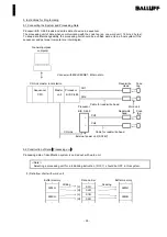
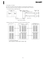
(1) Wiring Master Unit and Remote Unit
Refer to following wiring diagram for wiring master unit and remote unit with cable for CC-Link.
Master unit
Processor
Remote unit
DA
DA
DA
Terminal resistor
Terminal resistor
DB
DB
DB
DG
DG
DG
SLD
SLD
SLD
FG
+
24V
-
24G
FG
FG
<
>
Attention
"Terminal resistor" should be connected with DA-DB on both unit at the end of CC-Link.
In connecting terminal resistor with DA-DB, use the terminal resistor that attached with master unit.
(
)
Refer to the user's manual for CC-Link system master and local unit.
(2) Wiring of External Power Unit and Frame Ground
Refer to the above wiring diagram to connect external power unit 24V DC and frame ground.
(
)
C side of 24V DC power unit to the terminal indicated 24V , and - side to - .
[ ]
[
]
[ ]
[ ]
Connect frame ground to FG terminal.
[
]
Содержание BIS C-489-1 KBT02 Series
Страница 7: ... 4 2 3 Dimension ...