background image


EN


15 

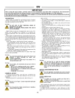
IMPORTANT 

Before  using  the  space  heater,  carefully  read  all  of  the  instructions  and  follow  them  scrupulously.  The  manufacturer 
cannot be held responsible for damage to persons and/or property caused by improper use of the equipment.


This instruction manual is an integral part of the equipment and must therefore be stored carefully and passed on with the 
unit in the event of a change of ownership.


DESCRIPTION 

Space  heaters


are  designed for  non-domestic  heating  of medium 

and large  ventilated premises, for  which a mobile heating system is 
required in accordance with EN 1596:2008. 


Warning 

DO  NOT  USE  TO  HEAT  HABITABLE  AREAS  OF 
RESIDENTIAL BUILDINGS. 
REFER  TO  NATIONAL  REGULATIONS  FOR  USE  IN 
PUBLIC BUILDINGS. 

 
Space  heaters  can  be  run  on  propane  gas  (G31)  or  on  L.P.G. 

(butane  G30  and  propane  G31)  according  to  the  different  gas 
categories indicated on Tab. I and shown on the heater identification 
plate. 

Space heaters are direct-combustion and forced convention units. 

Air is heated by the thermal energy generated during combustion and 
is then conveyed to the room to be heated along with the combustion 
products: the room MUST be suitably ventilated to ensure adequate 
air circulation.


Various safety devices  trip in the event of serious malfunction: 

  the  thermocouple  and  the  thermal  gas  valve  (M  and  M  DV 

models) trip to close the gas flow if the flame is irregular or if it 
goes out; 

  the electronic burner control unit trips if the flame is irregular or 

goes  out  (type  A  models):  the  reset  button  (8)  lights  up  with  a 
steady red light; 

   the overheating thermostat LI trips when the temperature of the 

combustion chamber exceeds the safety limit; 

In  each  of  the  cases  described  above,  the  space  heater  stops 

working in lock-out condition. 


Warning 

ВoЮ ЦЮЬЭ КХаКвЬ ТНОЧЭТПв ЭСО МКЮЬО oП ЭСО “ЛХoМФ” КЧН 

eliminate  it  before  restarting  the  heater  (see: 

“TROUBLźSHOOTINż”).


TвpО  A ЦoНОХЬ МКЧ  ЫОЬЭКЫЭ oЧХв  ТП ЫОЬОЭ ЛЮЭЭoЧ  “8” ТЬ 

pressed (red lamp is off). 
 

Warning 

For  A  models,  the  reset  button  (8)  may  have  different 
light types:


  light off: unit is working normally, flame is regular. 

  fast flashing: unit is running on starting cycle. 

  slow flashing: unit is in stand-by status,  waiting  for 

heating request. 

  steady light: lock-out status. 


GENERAL ADVICE 

The heater must be installed, set up and used in accordance with 

the  applicable  regulations  and  laws  relating  to  the  use  of  such 
equipment. 

Minimum distance from surrounding walls and/or ceiling: 2 m. 
 

Warning 

Do  not  use  the  heater  on  floors  made  with  flammable 
materials. 


Warning 

Use in basements or below ground level is hazardous 
because of gas stagnation. 


Make sure that: 

  The instructions in this manual are carefully followed; 

  The heater is not installed in an area where there is a high risk 

of fire or explosions; 

  No  flammable  materials  are  stored  in  the  vicinity  of  the  heater 

(minimum distance: 3 m); 

  There is no overheating of walls, or ceilings made of flammable 

materials, 

  All precautions have been taken to prevent fires; 

  The  premises  in  which  the  heater  is  installed  are  sufficiently 

ventilated  for  the  burner  requirements;  in  particular,  limits 
regarding air quality in the room to be heated must conform to 
applicable  national  or  local  laws  or,  in  the  absence  of  any 
standards and/or indications, to the provisions of EN 1596:2008: 

  minimum  room  volume  must  be  measured  with  thermal 

power/volume  ratio  equal  to  100  W/m

3

.  Room  volume  must 

NEVER be less than 100 m

3

  a  minimum  ventilation  area  of  25  cm

2

  per  kW  of  thermal 

power must be provided, the minimum being 250 cm

2

, divided 

equally between the upper and lower part; 

  Nothing  is  obstructing  the  aspiration  and  expulsion  of  air; 

movement  of  air  may  be  obstructed  in  various  ways  including 
placing covers or other objects on the heater or positioning the 
heater too near a wall or other large object; 

  The  generator  is  placed  near  a  power  switchboard  having 

specifications that conform to those declared; 

  The unit is placed in a stable position; 

  The hot air jet is directed towards the cylinder. 

  The heater is regularly monitored during operation and checked 

before being started; 

  At the beginning of each work period, a check is made that the 

fan  moves  freely  before  plugging  the  heater  into  the  electrical 
power supply; 

  At the end of each work period, the mains switch is disengaged 

and  supply  power  cord  removed,  main  gas  stopcock  is  closed 
and gas tube disengaged and sealed.  


Warning 

This  unit  may  not  be  used  by  persons  (including 
children)  with  reduced  physical,  sensorial  or  mental 
capacities  or  with  limited  experience  and  familiarity 
unless  they  are  under  supervision  or  instructed  on 
how  to  use  the  unit  by  the  person  responsible  for  its 
safety. 


INSTALLATION INSTRUCTIONS 

Warning 

All of the operations described in this section must be 
performed by professional and skilled personnel only. 


POWER CONNECTIONS 
Warning 

The  power  line  must  be  earthed  and  fitted  with  a 
residual current circuit breaker. 
The  power  cable  must  be  connected  to  a  panel  fitted 
with a cut-out. 

 
Before plugging the heater into the electrical power supply, check 

that the power supply specifications are the same as those stated on 
the identification plate. 

A  models  may  be  connected  to  a  room  thermostat  or  other 

accessories (such as the timer) by connecting to the thermostat plug 
(10). 

Содержание GP 30A

Страница 1: ...allu Biemmedue GP 85 C http www vseinstrumenti ru klimat teplovye_pushki gazovye ballu biemmedue gp_85a_c http www vseinstrumenti ru klimat teplovye_pushki gazovye ballu biemmedue gp_85a_c tab Respons...

Страница 2: ...1 51 GP 30A GP 45A GP 65A GP 85A Code 128...

Страница 3: ...l A 7 ELETTRODO DI IONIZZAZIONE Modello A ELECTRODE D IONISATION M A IONISATIONSELEKTRODE Modell A IONISATION ELECTRODE A model ELECTRODO DE IONIZACION Modelo A IONISATIE ELEKTRODE Model A ELEKTRODA J...

Страница 4: ...ve essere di almeno 2 m Attenzione No o o o p o materiali infiammabili Attenzione L o o o o o o o o pericoloso per il ristagno di gas propano e o butano Assicurarsi che Le istruzioni contenute nel pre...

Страница 5: ...tenzione po o utilizzato il raccordo opportuno per il collegamento alla bombola o bidone di gas Avvitare sempre prima il raccordo alla bombola e solo o o p o dotato di un raccordo girevole MODO I rego...

Страница 6: ...i modelli M attendere almeno 2 minuti per il completo raffreddamento della termocoppia prima di accend o o Attenzione S o o o o o o o opportuno ogni volta spegnere il generatore chiudendo prima il rub...

Страница 7: ...C C siano eccessive L C M elettronico per modelli A ed il collegamento elettrico ed eventualmente sostituirlo C T C L ia non si scalda e la valvola gas termica si chiude modello M M DV R premuto il pu...

Страница 8: ...8 LI L Attention To o o o o o ANOMALIES DE ONCTIONN M NT CAUS S T SOLUTIONS L o A p p o o pp o o 8 o o Attention L o o o 8 q p o q mod A p o l appareil fonctionne correctement clignotement rapide mac...

Страница 9: ...2 L E eurs Attention L q o p o p o Visser toujours le raccord d abord sur la bouteille et o i d un raccord rotatif MODE I G5 AT BG CY DK DE EE LT LV MK MT RO TR NL raccord G5 G2 avec fixation de type...

Страница 10: ...re pendant au moins 2 minutes pour permettre le refroidissement complet du thermocouple Attention S o o o q o o p pp l interrupteur 9 ou en agissant sur le thermostat C p o o p o p o o op po A A post...

Страница 11: ...fonctionner MODELE A 8 A V V bit V I combustion V V C C pas excessif L C M A C T C L rmocouple ne chauffe pas et la soupape de gaz thermique se referme M M DV R pendant au moins 30 secondes C D T M M...

Страница 12: ...ektronik Modelle A kann auf unterschiedliche Weise leuchten Ausgeschaltet o B Schnelles Blinken S aus Langsames Blinken Pausen oder Bereitschaftszustand in Erwartung der Anforderung des Heizbetriebs S...

Страница 13: ...en von Gasdruckreglern geliefert werden Achtung Es liegt in der Verantwortung des Installateurs sicherzustellen dass das richtige Fi Anschluss der Gasflasche verwendet wird Stets zuerst das Fitting un...

Страница 14: ...G F ermitteln STILLSETZUNG S G S 9 P 0 Modelle M M DV oder A zu schalten bzw der Raumluftthermostat M A Die Flamme erlischt dann und der Ventilatormotor schaltet sich aus D G Trennschalter auszuschalt...

Страница 15: ...n Modellen A und den S auswechseln D P S efekt T D T T M M M DV D E T T 30 S halten D P T D T Thermoelement defekt Modell M M DV D T auswechseln D I Flamme nicht Modell A D F bzw auswechseln A K einwa...

Страница 16: ...e of gas stagnation Make sure that The instructions in this manual are carefully followed The heater is not installed in an area where there is a high risk of fire or explosions No flammable materials...

Страница 17: ...equested seal for NL to install on G5 pressure regulator for NL TYPE II pressure regulator with G7 fitting for FI IE GB TYPE III pressure regulator with G9 fitting for SE NO Warning The seal of the fi...

Страница 18: ...ly used and avoids any future leak when removing the gas tube For type A model a post ventilation mode can be selected to cool the combustion chamber for 30 seconds when the heater is stopped To selec...

Страница 19: ...t and replace it if necessary T and gas valve closes M M DV models R eration keeping thermal gas valve button pressed for at least 13 seconds C R F M M DV models C I ctrode does not detect a flame A m...

Страница 20: ...stablecimiento 8 la luz roja fija desaparece A El pulsador 8 del q po o o o A p p o o p q o o regularmente p p o p o q o ciclo de arranque p p o o q p o d p p luz fija q o oq o RECOMENDACIONES GENERAL...

Страница 21: ...rlos se los debe girar en sentido contrario al de las agujas del reloj A Las o o o q o p L p o p p p o 2 El generador de aire caliente se suministra con tubo de gas a y bombonas de diferente tipo S A...

Страница 22: ...Para detener el funcionamiento del aparato se debe desplazar el 9 0 M M DV A A la llama se apaga y el motor del ventilador cesa de funcionar inmediatamente P desconectar el interruptor de seccionamie...

Страница 23: ...os L C para los M A C A C o de ser necesario E M M DV R 30 C E T M M DV C E presencia de llama modelo A E iarlo o sustituirlo I funcionamiento irregular del quemador modelo A D S A T A modelo A C aso...

Страница 24: ...RU 23 EN 1596 2008 G31 G30 G31 I 8 8 8 2 3 EN 1596 2008 100 3 100 3 25 2 250 2...

Страница 25: ...RU 24 10 2 I G5 AT BG CY DK DE EE LT LV MK MT RO TR NL G5 G2 G2 BE CZ ES FR HR HU LU PL PT SI SK G5 G1 G1 IT GR G5 G7 G7 FI IE GB G5 G9 G9 SE NO G5 G5R G5R CH NL NL G5 NL II G7 FI IE GB III G9 SE NO...

Страница 26: ...RU 25 9 0 9 8 9 0 9 30 PVC...

Страница 27: ...RU 26 8...

Страница 28: ...RU 27 RU 0001 11 B51 109599 74 2 II 109599 74 2 II 8 495 991 45 42 8 499 372 01 67 C IT AB51 B 02155 12 02 2013 12 02 2015 BIEMMEDUE S p A Via Industria 12 12062 Cherasco CN Italy...

Страница 29: ...RU 28 Ballu Biemmedue Ballu Biemmedue 1 2 1 2 3 4 5 6 7 8 9 12 ________________ 201...

Страница 30: ...______________________________________________________________________________ ______________________________________________________________________________ _________________________________________...

Страница 31: ...nipperen het apparaat is in pauze of verwarmingsverzoek vast licht het apparaat is in de geblokkeerde toestand ALGEMENE AANBEVELINGEN De installatie de afstelling en het gebruik van de luchtverhitter...

Страница 32: ...sen geleverd Afhankelijk van het land van bestemming kan de luchtverhitter met diverse soorten gasdrukregelaars worden geleverd Opgelet Het is de verantwoordelijkheid van de installateur om te control...

Страница 33: ...erhitter opnieuw in te schakelen Opgelet Als de luchtverhitter niet voortdurend wordt gebruikt is het verstandig hem elke keer uit te schakelen door eerst de gastoevoerkraan te sluiten en vervolgens o...

Страница 34: ...sche aansluiting en vervang deze eventueel C D C H thermische gasklep sluit model M M DV H thermische gasklep minstens 30 seconden ingedrukt C V D odel M M DV C eventueel D elektrode detecteert niet d...

Страница 35: ...o o o AL C NIA O LN Insta M 2 m Uwaga N o po o o op Uwaga Stosowanie w suterenach lub w pomieszczeniach po po o p po o zastoju propanu i lub butanu U Instrukcje zam przestrzegane G 3 S P nagrzewnica m...

Страница 36: ...wnica powietrza jest dostarczana razem z przewodem gazu gazu Uwaga I o o o p o po o o o o po p o o op o p o po o o o o TYP I G5 AT BG CY DK DE EE LT LV MK MT RO TR NL G5 G2 G2 BE CZ ES FR HR HU LU PL...

Страница 37: ...zycji C 8 J NIEPRA ID O O CI D IA ANIA PR C N I RODKI ARADC E ZATRZYMANIE 9 0 M M DV A termostatu otoczenia tylko modele A N Uwaga W przypadku modeli M p po o po o 2 o o o op Uwaga J o po p p 9 termos...

Страница 38: ...DEL M M DV wentylator nadal pracuje MODEL A 8 koloru czerwonego N S S gazu S powodu przegrzania komory spalania S zatkane S przewietrzane S S P S modelach M elektroniczny w modelach A oraz go S onowej...

Страница 39: ...LLAMPE RESET BUTTON PULSADOR RESTABLECIMIENTO RESETKNOP MET CONTROLELAMPJE PRZYCISK RESETOWANIA AP APPARECCHIATURA DI CONTROLLO COFFRET DE SECURITE STEUEREINHEIT CONTROL BOX APARATO DE CONTROL CONTROL...

Страница 40: ...ACI N D L T RMOPAR AFSTELSCHEMA THERMOKOPPEL SCHEMAT REGULACJI TERMOPARY A mm GP 30 33 GP 45 33 GP 65 50 5 GP 85 50 5 DESTINAZIONE EUROPEA D STINATION UROP NN BESTIMMUNGSGEBIET EUROPA EUROPE DESTINO E...

Страница 41: ...1 538 3 153 Pressione gas Pression gaz Betriebs druck Gas pressure P Gasdruk C bar 0 4 1 5 0 4 1 5 Portata d aria D Nenn Lufleistung Air output Capacidad aire Luchtdebiet N m3 h 1 100 1 250 Temperatur...

Страница 42: ...h 2 189 4 472 2 779 5 757 Pressione gas Pression gaz Betriebs druck Gas pressure P Gasdruk C bar 0 4 1 5 0 4 1 5 Portata d aria D Nenn Lufleistung Air output Capacidad aire Luchtdebiet N m3 h 1 950 2...

Страница 43: ...ONTAGGIO KIT RUOTE NOTICE DE MONTAGE DU KIT DE ROUS ANLEITUNG R DI MONTA DES RAEDERSATZES WHEELS KIT ASSEMBLY INSTRUCTION INSTRUCCIONES DE MONTAJE DEL KIT RUEDAS MONTAGE INSTRUCTIE WIELENKIT INSTRUKCJ...

Страница 44: ...E MANIGLIA NOTICE DE MONTAGE DU PIED DE LA POIGNEE ANL ITUN R DI MONTA D S USS S HANDGRIFFES FOOT HANDLE ASSEMBLY INSTRUCTION INSTRUCCIONES DE MONTAJE PIE MANILLA MONTAGE INSTRUCTIE VOETSTUK HANDGREEP...

Отзывы: