NOTE
As you can see, the parts of the sprockets that should be visible appear
as hidden lines. This shows that the complete area inside the outer chain
contour is defined as foreground.
Define the 2D hide situation in a way that the chain has an inner contour.
4
Respond to the prompt as follows:
Accept preview and exit command [Yes/No] <Yes>:
Enter
N
, press
ENTER
5
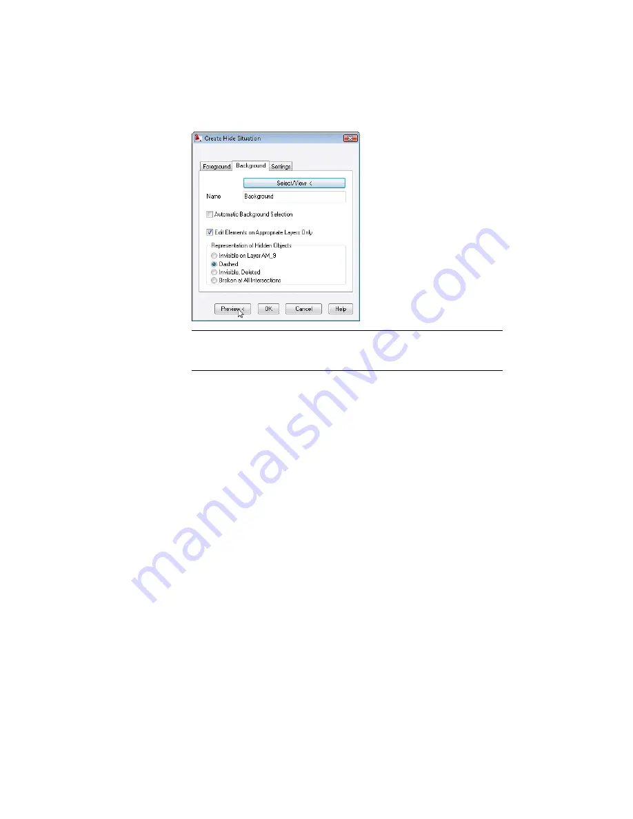
In the Create Hide Situation dialog box, Foreground tab, click Select Inner
Contours.
154 | Chapter 8 Working with 2D Hide and 2D Steel Shapes
Содержание 057A1-09A111-1001 - AutoCAD LT 2009
Страница 1: ...AutoCAD Mechanical 2009 User s Guide January 2008 ...
Страница 10: ...2 ...
Страница 50: ...42 ...
Страница 58: ...50 ...
Страница 106: ...98 ...
Страница 157: ...This is the end of this tutorial chapter Inserting Fits Lists 149 ...
Страница 158: ...150 ...
Страница 174: ...166 ...
Страница 179: ...3 In the Select a Screw dialog box select Socket Head Types Inserting Screw Connections 171 ...
Страница 180: ...4 Select ISO 4762 and Front View 172 Chapter 9 Working with Standard Parts ...
Страница 188: ...4 Select ISO 10642 and Front View 180 Chapter 9 Working with Standard Parts ...
Страница 212: ...204 ...
Страница 229: ...6 In the Set Value dialog box specify Column Material Value 8 Creating Parts Lists 221 ...
Страница 242: ...Save your file This is the end of this tutorial chapter 234 Chapter 10 Working with BOMs and Parts Lists ...
Страница 263: ...Save your file This is the end of this tutorial chapter Inserting Bearings 255 ...
Страница 264: ...256 ...
Страница 266: ...258 ...
Страница 282: ...274 ...
Страница 292: ...284 ...
Страница 306: ...298 ...
Страница 348: ...340 ...
Страница 366: ...Save your file This is the end of the tutorial chapter 358 Chapter 18 Designing and Calculating Cams ...
Страница 368: ...360 ...
Страница 406: ...398 ...
Страница 414: ......


