background image


59 

[1] Enter New Value for Adjustment 

From the 

Starting Basic Inspection Quantity

 menu, tap 

[1]

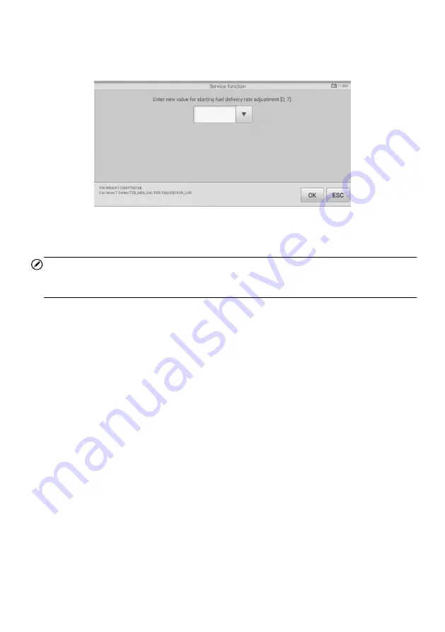
 and the screen displays as 

below. 


Figure 5-22 

Sample Enter New Value Screen 

After  entering  the  value,  tap 

OK

  to  save  the  value  to  the  tool.  Tap 

ESC

  to  exit  the 

operation. 

NOTE 

The data you input should be in the range given. If the input data is out of range, the tool 
will display a warning message “Permissible adjustment range exceeded.” 

[2] Reset Adjustment to 0 

Once the 

[2]

 is tapped, the tool will automatically reset the value to zero. 

[3]/[4] Store Data and Exit 

When the fuel delivery rate adjustment is completed, tap 

[3]

 to store the new value in the 

control units; or select 

[4]

 and 

OK

 to retain the old value. 

Injection Rate 

This function is used to adjust the injection volume. 

1.  Tap 

Injection Rate

 from the service functions menu to enter the service screen. 

2.  The tool communicates with the vehicle and reads the fault codes memory. Follow 

the on-screen instructions to finish this procedure.   

3.  The tool will display as below.  Press the corresponding number button to perform 

the desired function. 

Содержание MaxiCheck MX808TS

Страница 1: ... information available at the time of printing Autel reserves the right to make changes at any time without notice While information of this manual has been carefully checked for accuracy no guarantee is given for the completeness and correctness of the contents including but not limited to the product specifications functions and illustrations Autel will not be liable for any direct special incid...

Страница 2: ...Before using the device always refer to and follow the safety messages and applicable test procedures provided by the manufacturer of the vehicle or equipment being tested Use the device only as described in this manual Read understand and follow all safety messages and instructions in this manual Safety Messages Safety messages are provided to help prevent personal injury and equipment damage All...

Страница 3: ... hazardous voltages when the engine is running Keep a fire extinguisher suitable for gasoline chemical and electrical fires nearby Do not connect or disconnect any test equipment while the ignition is on or the engine is running Keep the test equipment dry clean free from oil water or grease Use a mild detergent on a clean cloth to clean the outside of the equipment as necessary Do not drive the v...

Страница 4: ...VEHICLE COMMUNICATION 19 GETTING STARTED 21 VEHICLE IDENTIFICATION 22 NAVIGATION 26 DIAGNOSIS 29 GENERIC OBDII OPERATIONS 40 EXITING DIAGNOSTICS 44 5 SERVICE 45 OIL RESET SERVICE 45 ELECTRONIC PARKING BRAKE EPB SERVICE 48 BATTERY MANAGEMENT SYSTEM BMS SERVICE 50 STEERING ANGLE SENSOR SAS SERVICE 55 DIESEL PARTICLE FILTER DPF SERVICE 57 IMMOBILIZER IMMO SERVICE 63 6 TPMS 65 GETTING STARTED 65 VEHIC...

Страница 5: ...ASK 110 TPMS MARKET 110 TPS PROG SETTING 110 AUTO UPDATE 110 CAR ORDER 111 SYSTEM SETTINGS 111 ABOUT 111 10 UPDATE 113 TABLET UPDATE 113 MAXIVCI MINI UPDATE 115 11 VCI MANAGER 116 12 SHOP MANAGER 118 VEHICLE HISTORY 119 WORKSHOP INFORMATION 120 CUSTOMER MANAGER 121 13 ACADEMY 123 14 REMOTE DESK 124 15 MAXIFIX 126 NAVIGATION 126 OPERATIONS 128 16 SUPPORT 134 PRODUCT REGISTRATION 134 SUPPORT SCREEN ...

Страница 6: ...HEAD ACCESSORIES 143 ACCESSORY ASSEMBLY 144 TECHNICAL SPECIFICATIONS 145 OPERATIONS 146 20 MAINTENANCE AND SERVICE 148 MAINTENANCE INSTRUCTIONS 148 TROUBLESHOOTING CHECKLIST 148 ABOUT BATTERY USAGE 149 SERVICE PROCEDURES 150 21 COMPLIANCE INFORMATION 152 FCC COMPLIANCE 152 SAR 153 RF WARNING STATEMENT 153 ROHS COMPLIANCE 153 CE COMPLIANCE 153 22 WARRANTY 154 ...

Страница 7: ... Tap OK Notes and Important Messages Notes A NOTE provides helpful information such as additional explanations tips and comments Important IMPORTANT indicates a situation which if not avoided may result in damage to the test equipment or vehicle Hyperlink Hyperlinks are available in electronic documents Blue italic text indicates a selectable hyperlink and blue underlined text indicates a website ...

Страница 8: ...services with ease There are two main components of the MX808TS system MX808TS tablet the central processor and monitor for the system MaxiVCI Mini Vehicle Communication Interface the device for accessing vehicle data This manual describes the construction and operation of both devices and how they work together to deliver diagnostics solutions MaxiCheck MX808TS Tablet Function Description Figure ...

Страница 9: ...l is below 90 C Red Illuminates red when the tablet is powered on and the battery level is below 15 5 Collapsible Stand extends from the back to allow hands free viewing of the tablet 6 Heat Sink 7 MaxiVCI Mini Holder 8 Built in Battery Figure 2 3 MaxiCheck MX808TS Top View 9 Mini USB OTG Port 10 Micro SD Card Slot holds the micro SD card 11 HDMI High Definition Multimedia Interface Port 12 USB Po...

Страница 10: ...he internal battery pack Technical Specifications Table 2 1 Specifications Item Description Recommended Use Indoor Operating System AndroidTM 4 4 2 KitKat Processor Cortex A9 processor 1 5 GHz Memory 64 GB Display 7 inch LCD capacitive touchscreen with 1024 x 600 resolution Connectivity Mini USB 2 0 USB 2 0 Wi Fi HDMI Type A Micro SD card supports up to 32 GB Sensors Light sensor for brightness au...

Страница 11: ... Diag H Protocol TP2 0 TP1 6 VCI Vehicle Communication Interface The wireless diagnostics interface MaxiVCI Mini is a small vehicle communication interface VCI used to connect to a vehicle s data link connector DLC and connect wirelessly with the tablet for vehicle data transmission Function Description 1 Vehicle Data Connector 16 Pin connects the MaxiVCI Mini to the vehicle s 16 pin DLC directly ...

Страница 12: ...reen when the device is successfully connected via the USB cable and is communicating with the vehicle Blue Lights solid blue when the device is successfully connected via Bluetooth but is not communicating with the vehicle Blinks blue when the device is successfully connected via Bluetooth and is communicating with the vehicle Technical Specifications Table 2 4 Specifications Item Description Com...

Страница 13: ...tes on 12 volt vehicle power which is received through the vehicle s DLC The unit powers on whenever it is connected to the vehicle s DLC Other Accessories USB Cable for test 2 m USB Cable for charging 90 cm USB External Power Adapter Together with the mini USB cable connects the tablet to the external DC power port for power supply ...

Страница 14: ...de the Lock icon to the left to enter the MaxiCheck Job Menu or slide to the right to unlock Figure 3 1 Sample MaxiCheck MX808TS Job Menu 1 Application Buttons 2 Locator and Navigation Buttons 3 Status Icons NOTE The tablet screen is locked by default when first powered on It is recommended to lock the screen to protect the information in the system and reduce the power consumption The touch scree...

Страница 15: ...k system settings menu and general tablet menu See Settings for details Update Checks for the latest update available for the MaxiCheck system and performs updates See Update for details VCI Manager Accesses VCI connection menu See VCI Manager for details Shop Manager Accesses Shop manager database to store workshop customer information and vehicle test history See Shop Manager for details Academy...

Страница 16: ...ose vehicle inspections See Digital Inspection for details Locator and Navigation Buttons Operations of the Navigation buttons at the bottom of the screen are described in the table below Table 3 2 Locator and Navigation Buttons Button Name Description Locator Indicates which screen you are on Swipe the screen left or right to view the previous or next screen Back Returns to the previous screen An...

Страница 17: ...rations of each button on the panel are described in the table below NOTE The shortcuts buttons will be highlighted when enabled and dimmed when disabled Table 3 3 System Status Icons Button Name Description Calculator Launches calculator when pressed Clock Launches clock when pressed BT Enables disables Bluetooth when pressed Wi Fi Enables disables Wi Fi when pressed Airplane Mode Enables disable...

Страница 18: ...let 1 Long press the Lock Power Button 2 Tap Power off option 3 Tap OK the tablet will turn off in a few seconds Reboot System In case of system crash long press the Lock Power button and tap Reboot option to reboot the system ...

Страница 19: ...will display atop the VCI navigation button at the bottom bar on the screen If communication has been established the MX808TS is ready to start vehicle diagnosis Vehicle Connection The tablet communicates with the vehicle via the Bluetooth connection provided by the MaxiVCI Mini To connect the MaxiVCI Mini to the test vehicle simply insert the Vehicle Data Connector on the MaxiVCI Mini into the ve...

Страница 20: ...is successful NOTE The USB communication method will take priority over Bluetooth communication if both are enabled No Communication Message A If the tablet is not connected to the MaxiVCI Mini correctly an Error message may display This indicates that the tablet cannot access the vehicle control module In this case please do the following check ups Check if the MaxiVCI Mini is powered up Check if...

Страница 21: ...hicle fuse There is a wiring fault of the vehicle or the adapter There is a circuit fault in the adapter Incorrect vehicle identification was entered Getting Started Ensure a communication link is established between the test vehicle and the tablet via the MaxiVCI Mini Vehicle Menu Layout When the tablet device is properly connected to the vehicle the platform is ready to start vehicle diagnosis T...

Страница 22: ...ean vehicle menu Asia Displays the Asian vehicle menu Search Searches for a specific vehicle make Cancel Exits the search screen or cancels an operation Vehicle Manufacturer Buttons To begin select the manufacturer button of the test vehicle followed by the vehicle mode and year Vehicle Identification The MaxiCheck diagnostics system supports four methods for Vehicle Identification 1 Auto VIN Scan...

Страница 23: ... 4 2 Sample Auto VIN Screen 3 Select Auto Detect Once the test vehicle is identified the screen will display the vehicle VIN Tap OK at the bottom right to confirm the vehicle VIN If the VIN does not match with the test vehicle s VIN enter VIN manually or tap Read to acquire VIN again Figure 4 3 Sample Auto Detect Screen 4 Tap Yes to confirm the vehicle profile or No if the information is not corre...

Страница 24: ...specific system to diagnose Figure 4 5 Sample Diagnostic Screen Manual VIN Input For vehicles not supporting the Auto VIN Scan function you may manually enter the vehicle VIN To perform Manual VIN Input 1 Tap the Diagnostics application button from the MaxiCheck Job Menu The Vehicle Menu displays 2 Tap the VIN Scan button on the top toolbar to open the dropdown list 3 Select Manual Input 4 Tap the...

Страница 25: ...lected after selecting the test vehicle manufacturer To perform Automatic Selection 1 Tap the Diagnostics application button from the MaxiCheck Job Menu The Vehicle Menu displays 2 Tap the manufacturer button of the test vehicle 3 Tap Automatic Selection and the VIN information will be acquired automatically Follow the on screen instruction to complete the operation Figure 4 7 Sample Selection Scr...

Страница 26: ...anual Selection Through a series of on screen prompts and selections the test vehicle is chosen If needed press the ESC button at the bottom right corner of the screen to return to previous screen Navigation Navigating the Diagnostics interface and selecting test are discussed in this section Diagnostics Screen Layout The diagnostics screens typically include four sections 1 Diagnostics Toolbar 2 ...

Страница 27: ... instructions or tips Save Opens a submenu and provides 3 options to save data Tap Take a Screenshot to take a screenshot of the current screen Tap Save All Data to save a PDF file use this save option when data displays on multiple screens Tap Save Report to save the data in a report form All saved data are stored in the Data Manager application for later reviews See Data Manager for details Data...

Страница 28: ...n Section 2 Voltage Icon displays the vehicle s voltage status Main Section The Main Section of the screen varies according to the stage of operations The Main Section can display vehicle identification selections the main menu test data messages instructions and other diagnostics information Function Buttons The displayed Function Buttons vary depending on the stage of operations Function Buttons...

Страница 29: ...ads to the desired test Tap the screen to make menu selections Diagnosis The Diagnostics application enables a data link to the electronic control system of the test vehicle for vehicle diagnosis The application performs functional tests retrieves vehicle diagnostics information such as trouble and event codes and live data from various vehicle control systems such as engine transmission ABS There...

Страница 30: ...st results These indicators are defined as follows Indicates that the scanned system may not support the code reading function or there is a communication error between the tablet and the control system Indicates that the vehicle control system has been detected but the tablet cannot accurately locate it Fault s Fault s indicates there is are detected fault code s present indicates the number of t...

Страница 31: ...he report form Quick Deletes codes A warning message screen will display to inform you of possible data loss when this function is selected OK Confirms the test result Continues to the system diagnosis after required system is selected by tapping the item in the Main Section Pause Suspends scanning and it will change to Continue button after tapping ESC Returns to the previous screen or exits Auto...

Страница 32: ...est vehicle s ECU Freeze Frame displays the freeze frame data of the DTCs Live Data retrieves and displays live data and parameters from the test vehicle s ECU Active Test provides specific subsystem and component tests Special Functions performs various component adaptations NOTE Toolbar functions such as saving and printing of test results can be performed throughout diagnostic testing Data logg...

Страница 33: ...on 2 Main Section the left column displays the item names the right column shows the specifications or descriptions 3 Function Button ESC or Back button is available tap it to exit after viewing Trouble Codes Read Codes This function retrieves and displays the DTCs from the vehicle s control system The Read Codes screen varies for each vehicle being tested On some vehicles freeze frame data can al...

Страница 34: ...nformation Freeze tap to view the freeze frame Search tap to search for related fault code information on Google ESC tap to return to the previous screen or exit the function Erase Codes After reading the retrieved codes and making appropriate vehicle repairs use this function to erase vehicle codes To erase codes 1 Tap Trouble Codes on the Function Menu then tap Erase Codes 2 A warning message di...

Страница 35: ...wn Button tap the drop down button on the right side of the parameter name to open a sub menu providing data display mode options Value Column displays the values of the parameter items Unit Column displays the unit for the parameters To change the unit mode tap the Setting button on the top toolbar and select a required mode See Unit for more information Display Mode There are four types of displ...

Страница 36: ...ales available x1 x2 x4 and x8 Zoom out Button exits full screen display 4 Digital Gauge Mode displays the parameters in form of a digital gauge graph Full Screen Display this option is only available in the waveform graph mode and primarily in Graph Merge status for data comparison Under this mode there are three control buttons available on the top right side of the screen To edit the waveform c...

Страница 37: ...the drop down button on the right side of the parameter name and select a data display mode Show tap this option to switch between the two options one displays the selected parameter items the other displays all the available items Setting tap this button to access setting menu to set the trigger mode recording duration and threshold values for data recording and define other control settings Ther...

Страница 38: ...ation screen for Record Setting to set the trigger type duration and trigger point for the data recording function a Trigger Type sets the trigger mode for data recording Manual and Auto There are four options available 1 Manual manually starts and stops data recording 2 DTC auto triggers data recording when any DTC is detected 3 DTC Check Mode auto triggers data recording when certain pre selecte...

Страница 39: ... may include toggling between two positions of a solenoid relay or switch Selecting Active Test opens a menu of test options that varies by make and model Selecting a menu option activates the test Follow on screen instructions while performing tests Procedures and instructions very by vehicles Some toggle and variable control tests display Active Test Controls at the top of the screen with data s...

Страница 40: ...fication testing verify repairs and perform a number of other services that are emissions related The OBD direct access option is also used for testing OBDII EOBD compliant vehicles that are not included in the Diagnostics database The diagnostics toolbar buttons at the top of the screen function the same as those available for specific vehicle diagnostics See Table 4 2 Diagnostics Toolbar Buttons...

Страница 41: ...erent communication protocols 3 Select a specific protocol under the Protocol option Wait for the OBDII Diagnostics Menu to display NOTE Tapping the button displayed beside the function name opens a bubble with additional function information 4 Select a function option to continue DTC FFD I M Readiness Live Data On Board Monitor Component Test Vehicle Information Vehicle Status NOTE Not all functi...

Страница 42: ...ferently so expect to see differences between makes Pending Codes These are codes that were generated during the last drive cycle but before the DTC actually sets two or more consecutive drive cycles are needed The intended use of this service is to assist the service technician after a vehicle repair and after clearing diagnostic information by reporting test results after a driving cycle a If a ...

Страница 43: ...oices Since DTCs Cleared displays the status of monitors since the last time the DTCs are erased This Driving Cycle displays the status of monitors since the beginning of the current drive cycle Live Data This function displays the real time PID data from ECU Displayed data includes analog inputs and outputs digital inputs and outputs and system status information broadcast on the vehicle data str...

Страница 44: ... are properly connected at all times during testing Exit all tests before disconnecting the test connection or powering down the tool To exit the Diagnostics application 1 From an active diagnostic screen tap the Back or ESC button to exit a diagnostic session step by step 2 Or tap the Vehicle Swap button on the diagnostics toolbar to return to the Vehicle Menu screen 3 From the Vehicle Menu scree...

Страница 45: ...en will display two application choices Diagnosis and Hot Functions Diagnosis enables the reading and clearing of codes which are sometimes necessary after completing certain special functions Hot Functions consists of sub functions of the selected special function Oil Reset Service Perform reset for the Engine Oil Life system which calculates an optimal oil life change interval depending on the v...

Страница 46: ...e Service application button from the MaxiCheck Job Menu 2 Tap Oil Reset button The vehicle manufacturer screen displays Tap VIN Scan or the vehicle make to acquire vehicle VIN information and tap Yes to confirm See Vehicle Identification for detail 3 Tap the desired function in the Oil Reset function list The list may vary by test vehicles 4 Follow the step by step on screen instruction to comple...

Страница 47: ...ounter 7 Tap on the value and then tap the Reset button on the right bottom of the screen 8 When the reset is done the availability would display as 100 Tap ESC to exit Figure 5 2 Sample Oil Reset Service Screen 2 Figure 5 3 Sample Oil Reset Service Screen 1 Figure 5 4 Sample Oil Reset Service Screen 3 ...

Страница 48: ... diagnostics work on the brake system This can be done from the tool menu Only perform maintenance work when the vehicle is stationary and on level ground Ensure that the EPB control system is reactivated after the maintenance work has been completed NOTE Autel accepts no responsibility for any accident or injury arising from the maintenance of the Electronic Parking Brake system To perform EPB fu...

Страница 49: ...cted after the following repairs Replacing an EMF control unit Replacing the parking brake button 1 Tap Continue to proceed with this service function or the Back button at the bottom left to exit 2 Tap on completed action to continue Figure 5 6 Sample EMF Start up Screen 1 Figure 5 7 Sample EMF Start up Screen 2 ...

Страница 50: ...for personal protection The installation position must be activated for the following repairs Replacement of brake pads Replacement of a brake caliper Replacement of an actuator Select Parking Brake Workshop Mode and follow the on screen instructions to perform a series of operations to start the brake pad after replacement When the operation is successfully completed a Completed successfully mess...

Страница 51: ... the battery reset Consult the vehicle manual for additional vehicle specific information Register Battery Replacement This option displays the mileage reading of last battery was replaced registers the battery replacement after replacing a new battery and informs the power management system that a new battery has been installed If the battery change is not registered the power management system w...

Страница 52: ...battery change and one before last A notice screen displays 5 Read carefully the complete information and press Continue 6 Check the battery capacity and the battery replacement information on the screen Figure 5 9 Sample BMS Function List Figure 5 10 Sample BMS Screen 1 Figure 5 11 Sample BMS Screen 2 ...

Страница 53: ... function 2 Register battery replacement 2 Read carefully the information on the screen Scroll through lists to view all the functions There are four functions 1 Enter battery replacement same capacity 2 Enter battery replacement different capacity 3 Enter battery replacement Changing from the normal lead acid battery white housing to AGM battery black housing 4 End service function Figure 5 13 Sa...

Страница 54: ...e on screen instructions to input the data matrix code of the newly installed battery that should be on the label of the battery Tap OK to continue 3 When the battery exchange is successfully entered tap Continue to exit Figure 5 14 Sample BMS Screen 5 Figure 5 15 Sample BMS Screen 6 Figure 5 16 Sample BMS Screen 7 ...

Страница 55: ...eplacement Any maintenance that involves opening the connector hub from the steering angle sensor to the column Any maintenance or repair work on the steering linkage steering gear or other related mechanism Wheel alignment or wheel track adjustment Accident repairs where damage to the steering angle sensor or assembly or any part of the steering system may have occurred NOTE 1 AUTEL accepts no re...

Страница 56: ...vehicle Figure 5 17 Sample SAS Function Menu Steering Angle Sensor Calibration This function allows users to perform steering angle sensor calibration and clear records The function options vary by vehicle 1 Tap Steering Angle Sensor Calibration from the SAS function menu to enter the function screen 2 Follow the on screen instructions to set the ignition on off as guided The vehicle battery volta...

Страница 57: ...han cars driven more with high load and speed In order for regeneration to take place a prolonged high exhaust temperature must be obtained In the event of the car being driven in such a way that regeneration is not possible i e frequent short journeys a diagnostic trouble code will eventually be registered in addition to the DPF light and Check Engine indicators displaying A service regeneration ...

Страница 58: ...ool at the same time This is dangerous and puts your life and the lives of other motors and pedestrians at risk Figure 5 20 Sample DPF Service Function Menu Starting Basic Inspection Quantity This function enables start fuel delivery matching 1 Tap Starting Basic Inspection Quantity from the service functions menu to enter the service screen 2 The tool communicates with the vehicle and reads the f...

Страница 59: ...tment to 0 Once the 2 is tapped the tool will automatically reset the value to zero 3 4 Store Data and Exit When the fuel delivery rate adjustment is completed tap 3 to store the new value in the control units or select 4 and OK to retain the old value Injection Rate This function is used to adjust the injection volume 1 Tap Injection Rate from the service functions menu to enter the service scree...

Страница 60: ... to 100 Once the 2 is pressed the tool will automatically reset the value to 100 3 4 Store Data and Exit When the injection volume adjustment is completed select 3 and OK to store the new value in the control units or select 4 and OK to retain the old value Injector Rate Adjustment This function is used to adjust the injector rate for individual cylinders 1 Tap Injection rate adjustment from the s...

Страница 61: ... and reads the fault codes memory Follow the on screen instructions to check the prerequisites before particle filter regeneration such as the fuel the time and driving style 3 If prerequisites are met the tool will ask your confirmation to proceed as below Tap Request to begin a regeneration or End to end the service function and exit Figure 5 25 Sample Regeneration Confirmation Screen 4 A series...

Страница 62: ...ation active jumps to Regeneration not active This behavior can be seen exclusively with the vehicle stationary with the engine Particle Filter Test It is advisable to carry out a series of particle filter tests as a result of constant DPF regeneration such as checking oil level oil change interval for diesel contamination swirl flaps backpressure sensors and particle filter soot remains 1 Tap Par...

Страница 63: ...anti theft protection than an audible alarm alone many auto insurance companies offer lower rates for vehicles that are equipped with an immobilizer As an anti theft device an immobilizer disables one of the systems needed to start a car s engine usually the fuel supply or the ignition This is accomplished by radio frequency identification between a transponder in the ignition key and a device cal...

Страница 64: ...he IMMO function list once displayed The list may vary by test vehicles NOTE 1 To complete key fob programming the Security Code will need to be required This can be done through the Security Code Read function in hot functions 2 Before programming please check and erase the fault codes Figure 5 29 Sample IMMO Note Screen 4 Read the on screen information carefully and follow the instructions to co...

Страница 65: ...S on the MaxiCheck Job Menu to access the TPMS Vehicle Menu 1 Top Toolbar Buttons refer to Table 6 1 Top Toolbar Buttons on Vehicle Menu for details 2 TPMS Service Access Methods OEM Part No Vehicle Manufacturer Buttons 3 Navigation Buttons 4 System Status Icons Top toolbar Buttons The operations of the Toolbar buttons at the top of the screen are described in the table below Figure 6 1 Sample TPM...

Страница 66: ... vehicle menu Korea Displays the Korean vehicle menu Japan Displays the Japanese vehicle menu Australia Displays the Australian vehicle menu Search Searches for a specific vehicle make Cancel Tap to exit the search screen or cancels an operation TPMS Service Access Methods OEM Part No Refer to TPMS by OEM Part No for details Vehicle Selection Select the manufacturer and follow the onscreen instruc...

Страница 67: ... test vehicle refer to Auto VIN Scan for details Or select a manufacturer brand on the TPMS Service Menu and follow the on screen instructions to select the vehicle make model and year Figure 6 2 Sample Vehicle Manufacturer Selection Figure 6 3 Sample Vehicle Model Selection ...

Страница 68: ...is supported Tap the vehicle year information button in the case of the above screen 2008 08 2017 01 indirect to display the Relearn Procedure follow the instructions to complete the operation Figure 6 4 Sample Vehicle Year Selection 1 Figure 6 5 Sample Indirect TPMS Selection Screen Figure 6 6 Sample TPMS Service Screen ...

Страница 69: ...isplays the triggered retrieved sensor IDs and new programmed sensor IDs 4 Relearn Tab displays the sensor Relearn procedure of the selected vehicle model The information of the test vehicle is displayed to the left of the four tabs The VCI connection status and the battery level of the test vehicle are displayed to the right of the four tabs NOTE Not all vehicles support Diagnosis function If the...

Страница 70: ...in the tool s upper right hand corner 3 On the tablet select the wheel you wish to trigger by either selecting the image of the wheel on the pictured vehicle or by selecting the corresponding wheel notation FL FR RR RL Tap Trigger button to activate this sensor 4 Once the sensor is successfully triggered the information of the sensor will display If the battery level of a sensor is low a red low b...

Страница 71: ...test procedure TPMS Diagnosis The Diagnosis function is used to check the status of the TPMS system This function requires connection with the test vehicle Establish Vehicle Communication The MX808TS Diagnostics Platform connects to the test vehicle using the MaxiVCI Mini Perform the following steps to establish communication between the vehicle and the tablet 1 Connect the MaxiVCI Mini to the veh...

Страница 72: ...osis on various vehicles conveniently by pairing the tablet separately to each of the MaxiVCI Mini devices connected to the different test vehicles via Bluetooth Without the need to repeat the plugging and unplugging procedure which is unavoidable through traditional wired connection Bluetooth connection saves you more time and provides higher efficiency USB Cable Connection Use the provided USB c...

Страница 73: ... the MaxiVCI Mini Contact technical support for assistance B A message will display if the MaxiVCI Mini is unable to establish a communication link The followings are the possible causes The MaxiVCI Mini is unable to establish a communication link with the vehicle The system selected for testing is not equipped on the vehicle There is a loose connection There is a blown vehicle fuse There is a wir...

Страница 74: ... vehicle ECU cannot recognize the sensor installed on the vehicle If the OBD function is not supported by the test vehicle the sensor ID saved in the TPMS ECU cannot be retrieved and only the sensor ID retrieved from sensor activation will display on the screen with a signal icon Detail If Diagnostics Trouble Codes DTCs are present in the TPMS ECU a yellow hazard icon displays in the DTC column an...

Страница 75: ...p Retry to establish communication with ECU again and retrieve sensor IDs and the DTCs present in the ECU Live Data Tap Live Data to view the data stream of the sensor information The Live Data screen displays all parameters by default Check the box before the parameters to display the Show icon on the bottom of the screen will be available and display blue Tap Show and the selected parameters wil...

Страница 76: ... Tap button to initiate desired vehicle lamp function test Sensor Programming The Programming function allows users to program the sensor data to the MX Sensor to replace existing sensors with low battery life and ones that are no longer functioning Figure 6 15 Sample Special Functions Screen Figure 6 14 Sample Live Data Screen ...

Страница 77: ... Programming screen displays as pictured below In this example the OBD function is not supported by the test vehicle and therefore the Copy by OBD function will not display Copy by Activation Once the sensors mounted on the vehicle have been triggered and the sensor and tire information displayed on the tool the Copy by Activation can use to program a new MX Sensor Select a wheel location on the d...

Страница 78: ...complete the programmed ID will display in the column to the right of the wheel designation In the pictured example the new ID is displayed to the right of the FL column Figure 6 19 Sample Copy by Activation Screen Figure 6 20 Sample Copy by Activation Complete Screen Figure 6 18 Sample Copy by Activation Confirmation Screen ...

Страница 79: ...Sensors Select a wheel location on the display and place a MX Sensor near the top right corner of the tablet Tap Copy by OBD to program the new MX Sensor When the programming is complete the programmed ID will display in the column to the right of the wheel designation In the pictured example the new ID is displayed to the right of the FR column By using Copy by OBD the sensor ID that is retrieved...

Страница 80: ... a decimal format A warning message will display if too many characters are entered The Copy by Input programming method uses the ID of the original sensor that is already stored within the TPMS ECU and therefore does not require the sensor be relearned if the new programmed sensor has been put in the same position Auto Create The Auto Create function is used to automatically create a random senso...

Страница 81: ...ave to be relearned to the TPMS ECU TPMS Relearn This function is used to write sensor IDs into the vehicle ECU for sensor recognition Relearn is needed to be performed when the new sensor IDs are different from the original sensor IDs stored within TPMS ECU There are THREE ways for Relearn Stationary Relearn Automatic Relearn OBD Relearn Stationary Relearn Stationary Relearn requires the vehicle ...

Страница 82: ...82 Then follow the Relearn Procedure to perform Stationary Relearn Figure 6 25 Sample Stationary Relearn Screen 2 Figure 6 24 Sample Stationary Relearn Screen 1 ...

Страница 83: ... OBDII Relearn The OBDII Relearn function allows the MX808TS tablet to directly write the TPMS sensor IDs to the TPMS module NOTE Not all the vehicles support the OBDII Relearn If the selected vehicle supports OBDII Relearn the OBDII Relearn button will display on the bottom of the screen Figure 6 27 Sample Automatic Relearn Screen 2 Figure 6 26 Sample Automatic Relearn Screen 1 ...

Страница 84: ...84 To perform the Relearn activate all four sensors Figure 6 28 Sample OBDII Relearn Screen 1 Figure 6 29 Sample OBDII Relearn Screen 2 ...

Страница 85: ...ensor s OEM part number is known this function is an efficient method to activate and program MX Sensors Application Scenarios The following are two typical scenarios in which this method is ideal In the workshop If the mounted sensor is faulty and the part number is known to the technician the technician can use this method to Check the original sensor and then write the information that was retr...

Страница 86: ...ght to find the correct OEM part number of the sensor on the test vehicle 2 Or tap the search box on the top right side of the screen to enter the part number A soft keyboard will display as below Enter the OEM Part No in the search box at the top right corner to complete the operation Figure 6 30 Sample OEM Part No Screen Figure 6 31 Sample OEM Part No Search Screen ...

Страница 87: ...his menu Tap Trigger on the bottom left of the screen to activate the original sensors and retrieve the sensor information The original sensor ID tire pressure tire temperature sensor battery and sensor frequency will populate the displayed table NOTE You can change the unit on the table header according to your preference Programming The programming function is used to program the sensor data to ...

Страница 88: ...entify the corresponding sensor ID This can be especially useful when programming multiple MX Sensors Support Support will display the correct vehicle types for the selected OEM part number To conduct additional procedures such as Diagnosis and Relearn select the correct test vehicle model and then tap Enter Vehicle at the bottom left of the screen Refer to TPMS Diagnosis and TPMS Relearn for more...

Страница 89: ...ty and reserve capacity which is vital to determine a battery s true health The MaxiBAS BT506 enables technicians to view the health status of the vehicle s battery and electrical system Together with the MaxiBAS BT506 this application can complete battery starter and alternator system tests MaxiBAS BT506 Tester Function Description Figure 7 1 MaxiBAS BT506 Tester Power Button Status LED Power LED...

Страница 90: ... charged Solid Red The device is in boot mode Flashing Red The battery level is low Please charge Power Sources The MaxiBAS BT506 tester can receive power from the following sources Internal battery pack AC DC power supply IMPORTANT Do not charge the battery when the temperature is below 0 C 32 F or above 45 C 113 F Internal Battery Pack The MaxiBAS BT506 tester can be powered with the internal re...

Страница 91: ...king buckling or leaking If you see any of these defects replace the battery Corroded loose or damaged cables and connections Repair or replace as needed Corrosion on the battery terminals and dirt or acid on the case top Clean the case and terminals using a wire brush and a mixture of water and baking soda Connect the Battery Tester To pair the BT506 with the MaxiCheck tablet 1 Press and hold the...

Страница 92: ...to the negative terminal of the battery Figure 7 3 Connecting to a Battery In vehicle Test In vehicle Test is used for testing batteries that are installed in a vehicle An in vehicle test includes Battery Test Starter Test and Generator Test These tests help determine the health status of the battery the starter and the generator IMPORTANT Before using the diagnostics functions download the desire...

Страница 93: ...the VIN information is filled 3 Confirm your battery information including voltage type standard and capacity Tap Next to continue Please refer to the table below for a list of buttons that may appear when accessing the functions Figure 7 5 Sample Vehicle Information Screen Figure 7 4 Sample Battery Test Screen ...

Страница 94: ... on the icon indicates the real time voltage of the tested battery In the battery test the button will turn green if the battery is good otherwise it will turn red Home Returns to the MaxiCheck Job Menu Next Tap to proceed Back Returns to the previous screen Exit Returns to the Job Menu ...

Страница 95: ...ructions Check the boxes once all required tasks are completed and tap Start Testing Figure 7 6 Sample Battery Screen 2 Wait until the test is completed The test results will be displayed on the tool Figure 7 7 Sample Battery Test Results Screen ...

Страница 96: ...ult Repair Tip Good Battery Battery is good Good Recharge Battery is good but insufficiently charged Recharge the battery Charge Retest Battery requires charge to determine its condition Bad Cell Replace the battery Replace Battery Replace the battery NOTE Please always complete the battery test before you proceed to the starter and generator tests ...

Страница 97: ... Test Follow the on screen instructions to complete the test Start the engine and let it idle The test results will appear as follows Figure 7 8 Sample Starter Screen Figure 7 9 Sample Starter Test Results Screen ...

Страница 98: ...ter Test Results Result Description Cranking Normal The starter is good Current Too Low Low momentary discharge capacity Voltage Too Low Low battery storage capacity Not Started The starter is not detected for starting ...

Страница 99: ...is loose or corroded Output Too High The generator is not properly connected to the ground The voltage adjuster is broken and needs replacement Ripple Too Large The commutation diode is broken No Output The cable is loose Some vehicles with power management systems do not provide path for charging due to the sufficient load capacity of the battery The generator or the voltage adjuster is broken an...

Страница 100: ...ery only Test Procedure To start the out vehicle test 1 Tap Out vehicle Test 2 Connect the tester clamps to the battery terminals 3 Select the appropriate battery type rating standard and CCA value Tap Start Testing to start the test Figure 7 11 Sample Out vehicle Test Screen 4 The test results will display in a few seconds Figure 7 12 Sample Out vehicle Test Results Screen ...

Страница 101: ...Battery meets required standards Good Recharge Battery is good but low on charge Fully charge the battery Check for causes of low charge Charge Retest Battery requires charge to determine its condition Replace Battery Battery fails to meet industry accepted standards Bad Cell Battery fails to meet industry accepted standards ...

Страница 102: ...on opens the file system menu Different file types are sorted separately under different options there are seven types of information files to be viewed or played back Operations Data Manager Operations are based on toolbar controls Details are explained in the following sections Image The Image section contains all captured screenshot images Figure 8 1 Sample Data Manager Main Screen ...

Страница 103: ...rmation Cancel Tap this button to close the editing toolbar or cancel file search Search Quickly locates the image file by entering the vehicle name test path file name or file info Info Tap this button to display the details Print Tap this button to print the selected image For details see Printing Setting Delete Tap this button to delete the selected image To edit image information 1 Tap the Dat...

Страница 104: ...lication from the MaxiCheck Job Menu 2 Tap Image to access the JPG database 3 Tap the image to display the editing toolbar 4 Tap the Delete button and then Delete image then the selected images will be deleted Report The Report section stores diagnostics information of the vehicle and forms a diagnostics report for user to share To share a report 1 Tap the Data Manager application from the MaxiChe...

Страница 105: ...ection stores and displays all saved data PDF files Select a PDF file from the database to display The standard Adobe Reader application is used for file viewing and editing please refer to the associated Adobe Reader manual for detailed instructions Review Data The Review Data section allows playback of the recorded data frames of live data streams Figure 8 4 Sharing Report Screen 1 Figure 8 5 Sh...

Страница 106: ...ta playback Apps Uninstall This section manages the firmware applications installed on the MaxiCheck Diagnostics System Select this section to open a management screen on which you all the available vehicle diagnostics application can be reviewed Tap the vehicle firmware you want to delete a blue tick at the upper right corner of the firmware will display Tap the Delete button on the top bar and t...

Страница 107: ...g section allows you to launch Support platform directly to view all records of all sent or unsent saved data loggings on the diagnostics system For more details please refer to Data Logging Figure 8 7 Sample Vehicle Management Screen ...

Страница 108: ...tem To adjust the unit setting 1 Tap the Settings application on the MaxiCheck Job Menu 2 Tap the Unit option on the left column 3 Select the appropriate measurement unit Metric or Imperial A check mark will display to the right of the selected unit 4 Tap the Home button on the top left corner to return to the MaxiCheck Job Menu Or select another setting option for system setup Language This optio...

Страница 109: ...Support Downloads Diagnostic Tool and install to your PC 2 Double click the setup exe file 3 Select the installation language and the wizard will load momentarily 4 Follow the instructions on the screen and click Next to continue 5 Click Install The printer driver program will be installed onto the PC 6 Click Finish to complete the installation NOTE The PC and the tablet must be connected to the s...

Страница 110: ...s option allows you to set the TPMS market region The available options are Europe Market North America Market Korea Market Japan Market and Australia Market A check mark will display to the right of the selected item TPS Prog Setting This option allows you to set the TPS program pressure limit The available options are Prog Pressure 69Kpa 10PSI and No Prog Pressure Limit A check mark will display...

Страница 111: ...p Switcher function 1 Tap the Settings application on the MaxiCheck Job Menu 2 Tap the System settings option on the left column 3 Tap the App Switcher option on the left column 4 Check the box beside Always show the App Switcher on the right side of the screen then the App Switcher icon will display Short pressing the App Switcher icon opens a control panel Tap a specific app shortcut button to a...

Страница 112: ...ap the About option on the left column The product information screen displays on the right 3 Tap the Home button on the top left corner to return to the MaxiCheck Job Menu or select another setting to adjust ...

Страница 113: ...typically by adding new tests new model coverage or by adding enhanced applications Update Operation The tablet automatically searches for available updates for all of the MaxiCheck software when it is connected to the Internet Any updates that are found can be downloaded and installed on the device This section describes update procedures in the MaxiCheck System Figure 10 1 Sample Update Screen 1...

Страница 114: ...ems Tap Get to update the item Tap Pause to suspend the update Tap Continue to resume the update To update software 1 Ensure the tablet is connected to a power source and has a stable connection with the Internet 2 Tap the Update application button from the MaxiCheck Job Menu or tap the received notification message or tap the Update icon on Vehicle Menu in Diagnostics application The Update appli...

Страница 115: ...e MaxiCheck Job Menu of the tablet 4 Select Update from the connection mode list 5 The current version and the latest version of the VCI software will be displayed after a few seconds Click Update Now to update the VCI software if available Update via PC To update the MaxiVCI Mini via PC 1 Download the Maxi PC Suite from www autel com Support Downloads Diagnostic Tools and install it onto your win...

Страница 116: ...tics Platform to the vehicle through the VCI 3 Tap VCI Manager on the MaxiCheck Job Menu of the tablet 4 Tap VCI BT from the connection mode list 5 Toggle Bluetooth ON The device will start searching for available units for pairing 6 Depending on the VCI you use the device name may appear as Maxi suffixed with the serial number Select the appropriate device for pairing 7 When paired successfully t...

Страница 117: ...connection mode list 5 The current version and the latest version of the VCI will appear Tap Update now to update the VCI BAS Update updates BAS firmware via the Internet after the tablet connects the BT506 device via Bluetooth To update the BT506 1 Power on the tablet and the BT506 2 Connect the BT506 device to the tablet via Bluetooth 3 Tap VCI Manager on the MaxiCheck Job Menu of the tablet 4 T...

Страница 118: ...n Name Description Back Returns to the previous screen Diagnostics Tap this button to access vehicle Diagnostics menu Enter Edit Displays the editing toolbar to print or delete the selected file Delete Deletes the selected vehicle record Search Enters the vehicle name or test path to retrieve the vehicle record Cancel Cancels edit or file search Edit Edits information for the displayed file Add Ac...

Страница 119: ...ottom of the thumbnail of a vehicle record item 4 Or tap the vehicle record thumbnail to view record 5 A Historical Test record sheet displays Check the recorded information of the recorded test vehicle and tap the Diagnostics button on the upper right corner 6 The vehicle s Diagnostics screen displays Now a new diagnostics session is activated see Diagnostics for detailed instructions on vehicle ...

Страница 120: ...ult Adding one of the information will automatically associate the other item in the record sheet provided that the later one exists 6 Tap Add to Customer to supplement the Historical Test record sheet to an existing customer account or add a new associated account with the test vehicle record See Customer Manager for more information 7 Tap Done to save the updated record sheet or tap Cancel to ex...

Страница 121: ...r account 1 Tap the Shop Manager application on the MaxiCheck Job Menu 2 Select Customer Manager 3 Tap the Add Account button An empty information form displays tap each field to input the appropriate information NOTE Required fields are noted 4 Tap the photo frame beside the Name chart to add a photo A sub menu displays select Take Photo to take a new photo for the account or select Choose Photo ...

Страница 122: ...emented and enter updated information 6 Tap Done to save the updated information or tap Cancel to exit without saving To delete a customer account 1 Tap the Shop Manager application on the MaxiCheck Job Menu 2 Tap Customer Manager 3 Select a customer account by tapping the corresponding name card A Customer Information sheet displays 4 Tap the Edit button on the top toolbar to start editing 5 Tap ...

Страница 123: ...l articles and technical bulletins produced by top notch technicians and product experts Please view the materials that are saved on the tablet or view technical articles from our online forum by clicking the links displayed under this application ...

Страница 124: ...aracteristics and will not change later on Make sure the tablet is connected to the Internet before launching the Remote Desk application so that the tablet is accessible to receive remote support from the third party To receive remote support from a partner 1 Power on the tablet 2 Tap the Remote Desk application on the MaxiCheck Job Menu The TeamViewer screen displays and the device ID is generat...

Страница 125: ...125 6 Tap Allow to accept or tap Deny to reject Refer to the associated TeamViewer documents for additional information ...

Страница 126: ...ed to quickly lead you to the root cause of a particular problem on the test vehicle Navigation You need to register the device to your online account before launching the MaxiFix platform see Product Registration for details The MaxiFix screen layout consists of three main areas 1 The Header the tool bar across the top of the screen which allows you to select vehicles and perform searches 2 The M...

Страница 127: ...already done so tap the Select Vehicle button on the Header 2 Select the year of the vehicle from the list 3 Select the make of the vehicle from the list 4 Select the model of the vehicle from the list 5 Select the submodel of the vehicle from the list 6 Select the engine of the vehicle from the list After completing the vehicle selection procedure the identified vehicle is shown on the Header Ter...

Страница 128: ...nt you can ask the MaxiFix community for help by clicking Ask on the Navigation Menu at the bottom of the screen Adopted The Adopted icon that displays at the top right side of a Tip screen indicates that the related Tip has been adopted by at least 1 technician in the community If a tip has helped you to solve a repair problem you are encouraged to give an Adopted count to the tip Each member is ...

Страница 129: ...his filter can be canceled anytime by clicking the Remove All Filters button and the default setting will be restored to display questions about all vehicle makes Search Fix Features Search Fix the second option on the Navigation Menu at the bottom of the screen presents search results for the specified vehicle Search results are listed in various categories All includes all search results includi...

Страница 130: ...ix the fourth option on the Navigation Menu at the bottom of the screen opens your personal MaxiFix screen To access the features on My MaxiFix screen you can select from the tabs My Questions opens a list with links to the opened questions that you have posted to the community My Cases opens a list with links to the closed questions and tips that you have contributed to the community Marked Posts...

Страница 131: ...ew your personal profile by clicking on your account ID or My Profile in My MaxiFix section or edit portrait where applicable and visit other community members profile by clicking their portrait Information included in your profile determines how you are presented to the community and what type of information will be sent to you from the community My Messages My Messages the fifth option on the Na...

Страница 132: ...Messages screen first then tap Adopted Answer and select Close Question Tap the Cancel button to cancel your submission and return to My Messages screen It is strongly recommended to share your repair solutions before closing a question Your question will be converted to a MaxiFix Community Tip after closing Score Rewarding System A score of 4 is awarded if your answer is selected as the Adopted A...

Страница 133: ... please use the contact form Select Support from the Navigation Menu to open the comment window To allow the administrator to respond to your question or issue the following information should be provided Your name A contact email address A contact phone number ...

Страница 134: ... a new member to Autel click Register on the left side of the screen to create your Autel ID 4 Enter your personal information Fields marked with an asterisk are mandatory 5 Enter your email address then click Request You will receive an email from Autel with your verification code Open the email and copy the code into the proper input box 6 Set a password for your account and enter the password a...

Страница 135: ...nu select one subject from the main menu to display the corresponding functional interface on the right My Account The My Account screen displays the comprehensive information of the user and the product which is synchronized with the on line registered account including User Info Device Info Update Info and Service Info Personal Info The User Info and Device Info are both included under the Perso...

Страница 136: ...ion with as well as ask for technical advices or offer technical supports to all other members in Autel s online support communities Figure 16 2 Sample Communities Home Screen To start a discussion 1 Tap Start a discussion on the Communities Home screen A list of the major forums is displayed 2 Select the appropriate device heading For example if you are going to ask a question about the MaxiCheck...

Страница 137: ...unities as well as to find out other online users Avatar allows you to select an image to set as your personal Avatar to be displayed in the communities Stuff displays all the discussions you ve posted at various forums in a list Data Logging The Data Logging section keeps records of all sent or unsent saved data loggings on the diagnostics system The support personnel receive and process the subm...

Страница 138: ... Autel s online member account and shopping and payment procedures Account displays questions and answers about the use of Autel s online user account Shopping displays questions and answers about online product purchase methods or procedures Payment displays questions and answers about online payment methods or procedures ...

Страница 139: ...itional in automotive service sites Figure 17 1 Sample Quick Link Screen To open a quick link 1 Tap the Quick Link application on the MaxiCheck Job Menu The Quick Link application screen displays 2 Select a website thumbnail from the main section The Chrome browser is launched and the selected website is opened ...

Страница 140: ... Function Viewer application on the MaxiCheck Job Menu The Function Viewer application screen displays 2 Tap the tool name on the top left to drop down the tool list tap the one you want to search Figure 18 1 Sample Function Viewer Screen 1 3 Tap the vehicle brand model and year you want to search 4 All the functions support by the selected tool for the selected vehicle displays with three column ...

Страница 141: ...st tap the one you want to search 3 Type in the function you want to search to the top right search column All the vehicles with this function will be listed with 8 columns the Brand Model Year System Sub system Function Sub function and Version NOTE Fuzzy search is supported type in part of the function you want to search can also find you all the related Figure 18 3 Sample Function Viewer Screen...

Страница 142: ...lear pathways or clogged areas When inspection is completed carefully withdraw the imager head from the inspected area The imager head cable is waterproof to a depth of 3 m 10 ft Greater depths may cause leakage into the imager head cable electric shock or tool damage The working temperature of the imager head is between 32 F 0 C and 113 F 45 C Check Ups FOR AUTOMOBILES Ensure the automobile is no...

Страница 143: ...and agile operation USB Cable connects the Inspection Camera to the MaxiCheck tablet Imager Head Accessories Mirror helps to look around corners and see the unreachable areas Hook unclogs obstacles and picks up wires in the pipes or confined areas Magnet picks up small metal objects such as dropped rings or screws Figure 19 1 Inspection Camera Figure 19 2 8 5 mm Imager Head Accessories ...

Страница 144: ...l metal objects such as dropped rings or screws Accessory Assembly 8 5 mm Imager Head The three accessories including the Magnet Hook and Mirror can be attached to the Imager Head in the same manner described below 1 Hold the accessory and the imager head 2 Slip the end of the accessory over the imager head and then fix the accessory ...

Страница 145: ...ssory Technical Specifications Table 19 1 Technical Specifications Item Description Optimal Viewing Distance 0 79 to 2 36 2 to 6 cm with 8 5 mm diameter imager head 0 79 to 2 36 2 to 6 cm with 5 5 mm diameter imager head Resolution JPG images 640 x 480 AVI videos 320 x 240 Operating Temperature Main Unit 0 to 55 C 32 to 131 F ambient Cable 10 to 70 C 14 to 158 F Storage Temperature 20 to 75 C 4 to...

Страница 146: ... in the view finder by adjusting and properly locating the imager head cable 5 Tap the blue ring on the screen The view finder now displays the captured picture and auto saves the taken photo 6 Tap the thumbnail image on the top right corner of the screen to view the stored image Slide the screen left and right to view the images 7 Tap on the selected image and the edit toolbar instantly displays ...

Страница 147: ...t recording 7 Tap the red circle again to stop recording The recorded video is automatically saved 8 Tap the gallery icon at the bottom right corner to review all recorded videos 9 Select the corresponding button on the upper right corner to search or delete a video ...

Страница 148: ...lean with a damp cloth Do not attempt to disassemble your tablet or the MaxiVCI Mini Do not drop or cause severe impact to the devices Use only authorized battery chargers and accessories Any malfunction or damage caused by the use of unauthorized battery charger and accessories will void the limited product warranty Ensure that the battery charger does not come in contact with conductive objects ...

Страница 149: ...rrect replacement or tampering with the battery pack may cause an explosion Do not use a damaged battery charger Do not disassemble or open crush bend or deform puncture or shred Do not modify or remanufacture attempt to insert foreign objects into the battery expose to fire explosion or other hazard Make sure to use the charger and USB cables only that come together in the package If you use the ...

Страница 150: ...m EST Website www autel com Email sales autel com ussupport autel com Address 36 Harbor Park Drive Port Washington New York USA 11050 AUTEL EUROPE Phone 0049 0 6103 2000520 Website www autel eu Email sales eu autel com support eu autel com Address Landsberger Str 408 4 OG 81241 München Germany AUTEL CHINA HQ Phone 0086 755 2267 2493 Website www autel com Email sales auteltech net support autel com...

Страница 151: ...ontact name Return address Telephone number Product name Complete description of the problem Proof of purchase for warranty repairs Preferred method of payment for non warranty repairs NOTE For non warranty repairs payment can be made with Visa Master Card or with approved credit terms Send the device to your local agent or to the below address 8th Floor Building B1 Zhiyuan Xueyuan Road Xili Nansh...

Страница 152: ...E This equipment has been tested and found to comply with the limits for a Class B digital device pursuant to Part 15 of the FCC Rules These limits are designed to provide reasonable protection against harmful interference in a residential installation This equipment generates uses and can radiate radio frequency energy and if not installed and used in accordance with the instructions may cause ha...

Страница 153: ...s Although the SAR is determined at the highest certified power level the actual SAR level of the device while operating can be well below the maximum value This is because the device is designed to operate at multiple power levels so as to use only the power required to reach the network To avoid the possibility of exceeding the FCC radio frequency exposure limits human proximity to antenna shoul...

Страница 154: ...bove limitations may not apply to you This warranty does not apply to 1 Products subjected to abnormal use or conditions accident mishandling neglect unauthorized alteration misuse improper installation or repair or improper storage 2 Products whose mechanical serial number or electronic serial number has been removed altered or defaced 3 Damage from exposure to excessive temperatures or extreme e...

Отзывы: