


10
Power Sources
The tablet can receive power from any of the following sources:
Internal Battery Pack
External Power Supply
Internal Battery Pack
The tablet can be powered with the internal rechargeable battery, which if fully charged
can provide sufficient power for about 7 hours of continuous operation.
External Power Supply
The tablet can be powered from a wall socket using the USB charging cable and the USB
external power adapter. The external power supply also charges the internal battery pack.
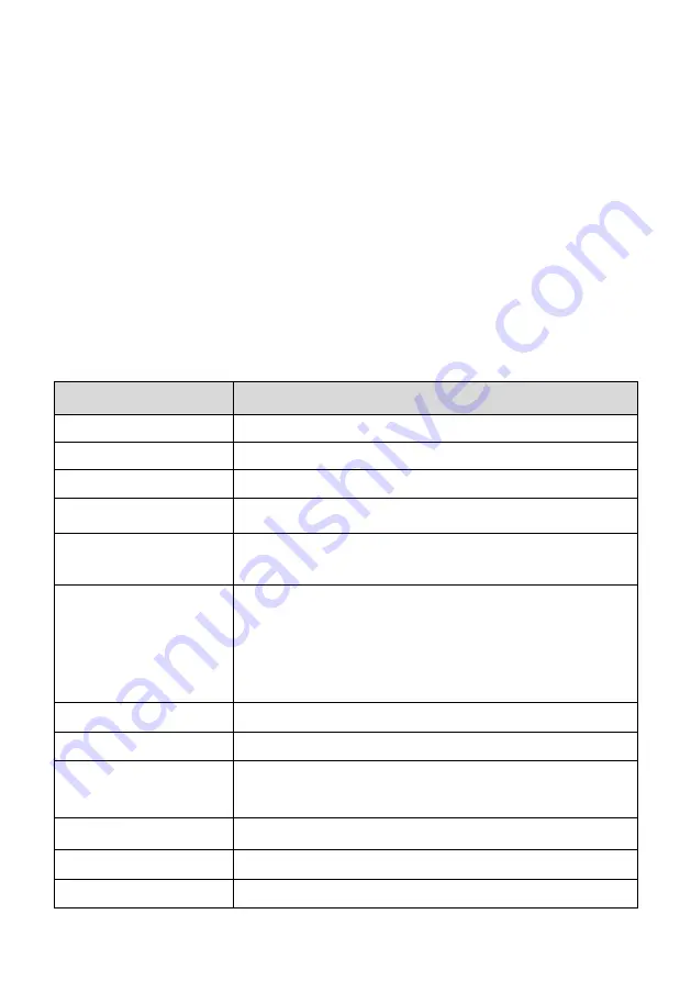
Technical Specifications
Table 2-1
Specifications
Item
Description
Recommended Use
Indoor
Operating System
Android
TM
4.4.2, KitKat
Processor
Cortex-A9 processor (1.5 GHz)
Memory
64 GB
Display
7-inch LCD capacitive touchscreen with 1024 x 600
resolution
Connectivity
Mini USB 2.0
USB 2.0
Wi-Fi
HDMI Type A
Micro SD card (supports up to 32 GB)
Sensors
Light sensor for brightness auto changing
Audio Output
Buzzer
Power and Battery
3.7 V/5000 mAh lithium-polymer battery
Charges via 5 V DC power supply
Tested Battery Life
Around 7 hours of continuous use
Battery Charging Input
5 V/1.5 A
Power Consumption
600 mA (LCD on with default brightness, Wi-Fi on) @3.7 V


