74
1. Place the cam arms, thrust washers, and cam arm
pivot pins (pivot pin heads opposite direction of rota-
tion) into the moveable drive sheave and secure with
new lock nuts. Tighten to 48 in.-lb.
NOTE: The drive clutch rotates clockwise.
2. Align the spider and movable sheave timing marks; then
making sure the cam arms are properly positioned, drop
the spider into position in the moveable sheave.
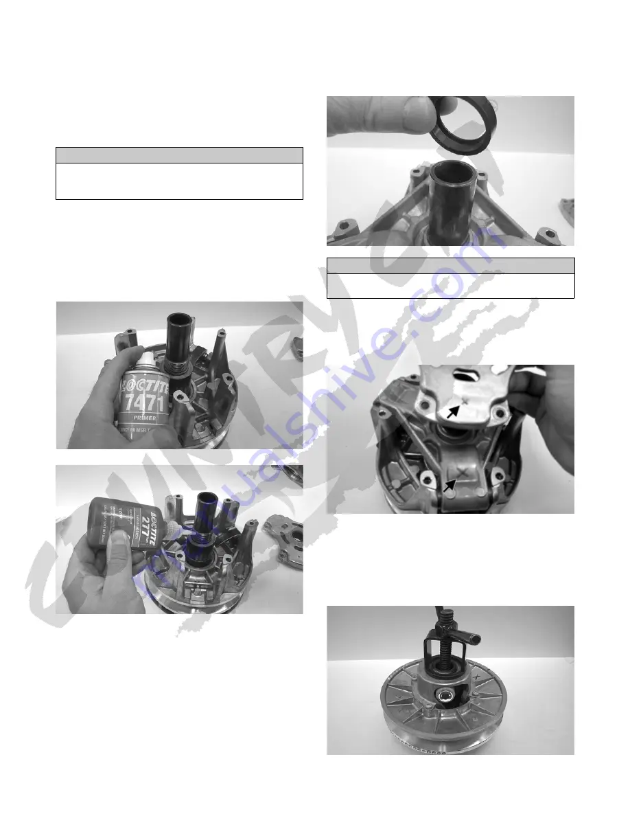
3. Place the movable sheave, spacer washers, and
spider into position on the stationary sheave hub.
Make sure all threads are clean and free of oily
residue. Apply Loctite Primer #7471 and allow to
dry per instructions; then apply red Loctite #277 to
the threads of the stationary sheave and spider.
Tighten the spider to 265 ft-lb.
WC641
WC642
NOTE: Allow the Loctite to cure at room tempera-
ture for 24 hours.
NOTE: Grasp the moveable sheave and lift it
upward; then release it. It must move freely and not
bind at any point.
4. With the head of each cam arm pin positioned away
from the direction of the drive clutch rotation, install
the cam arms.
NOTE: The drive clutch rotates clockwise.
5. Secure the cam arm pins with new lock nuts and
tighten to 48 in.-lb.
6. Place the shift stop into position with the relief
towards the spider.
WC655
7. Install the spring.
8. Align the match marks (X) and install the clutch cover
and secure with six cap screws. Tighten using a criss-
cross pattern to 120 in.-lb.
WC653A
DRIVEN CLUTCH
Disassembling
1. Install the clutch into an appropriate driven clutch
compressor tool. Finger-tighten the wing nut to
tighten.
WC638
2. Remove the driven cam; then remove the spider assembly.
CAUTION
Failure to align the spider and movable sheave timing
marks will cause drive clutch to be out of balance
resulting in clutch and crankshaft damage.
CAUTION
Install the shift stop cam with the relief facing down or
severe engine damage could occur.


