Setup
Page 31 of 178
Output Assembly Size
When using Scheduled ControlNet this is the size of the output data (being sent from
the ControlNet Router) that can be mapped for the PLC5 emulation. See the
Scheduled ControlNet
section.
Table 3.2 - General configuration parameters
The module can operate as either a ControlNet Target or a ControlNet Originator. The below
sections will provide more information regarding these operational modes.
3.5.1.
T
ARGET
A Logix controller can own the ControlNet Router over ControlNet using a scheduled
ControlNet connection when the ControlNet Router is operating as a ControlNet target. This
will allow the ControlNet Router to exchange data with the Logix controller using the input
and output assembly of the scheduled ControlNet connection. Data from EtherNet/IP or
Modbus TCP devices can be mapped to the Logix controller over ControlNet.
The user will need to add the ControlNet Router to the Logix IO tree under a ControlNet bridge
(e.g. 1756-CNB/R). After the module has been added, the ControlNet connection will need to
be scheduled with RSNetworx for ControlNet.
3.5.1.1.
STUDIO / LOGIX 5000 CONFIGURATION
A.
ADD MODULE TO CONTROLNET I/O CONFIGURATION (USING SCHEDULED
CONTROLNET)
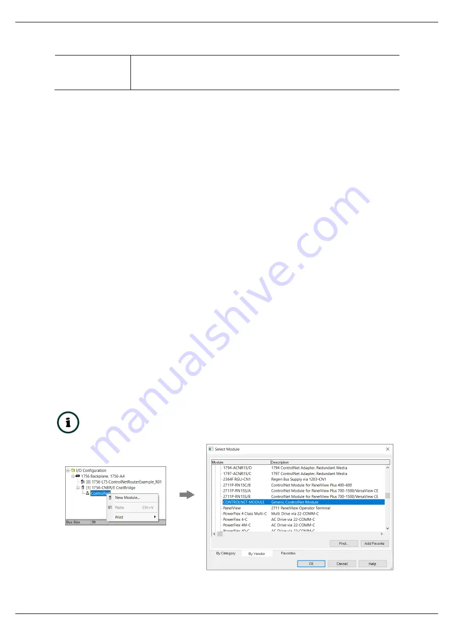
The ControlNet Router can be added to the Logix 5000 I/O tree under a ControlNet bridge
(e.g. 1756-CNB). The module will need to be added as a generic ControlNet module. This is
done by right clicking on the ControlNet Bridge in the Logix 5000 and selecting
New Module
after which the
CONTROLNET-MODULE
is selected to be added as shown in the figure below.
NOTE:
See the next section for importing the configuration (L5X).
Figure 3.18 - Add a Generic ControlNet Module in Logix 5000


