Chapter 4 Operations for Each Function
4-54
When this software is activated in the MG3710/MG3740 mode;
When reading a waveform pattern, the data is read from the conversion
source file and the RMS and Peak values are calculated and displayed.
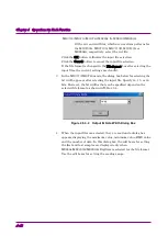
Click the RMS Value text box, and then enter the RMS value of the
post-conversion waveform that is actually used for this option. The Peak
value changes in conjunction with the RMS value. On the other hand, if
you click the Peak Value button to set the peak value, the RMS value is
also correspondingly changed.
Figure 4.5.4-5 RMS Value Dialog Box
Normally, the Normalizing checkbox is selected and the RMS and Peak
values are automatically specified, but the values can be manually
specified to adjust the characteristics for signals that have a crest factor
larger than 17 dB.
Note that the RF output level reliability for the MS2830A is specified
assuming the following RMS values.
Table 4.5.4-5 RMS Setting Range of Guaranteed Output Level
Bit Width
RMS-value setting range
14 bit
819 to 1634
15 bit
1638 to 3269
16 bit
3276 to 6537
■
Setting unit (available for ASCII1, ASCII2, ASCII3, and
MS269x/MS2830A/MS2840A Digitizer)
Click
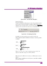
in the Unit symbol list box, and then select the unit.
sample, symbol, chip, or none can be selected as the unit.
This setting is applied to the screen display unit when the waveform
pattern is used.
Figure 4.5.4-6 Unit Symbol Dialog Box


