4.5 File Conversion on Convert Screen
4-51
Figure 4.5.4-2 Low Pass Filter Dialog Box
■
Setting Normalizing
To apply the RMS (Route Mean Square) value of the standard waveform
pattern used by the MG3700A/MG3710A/MG3710E/MG3740A to the
amplitude of the waveform pattern to be converted, click the Normalizing
check box of the conversion source file to leave a checkmark ( ).
Figure 4.5.4-3 Normalizing Check Box
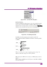
The RMS value of the standard waveform pattern used by the
MG3700A/MG3710A/MG3710E/MG3740A Indicates the following RMS
I
and RMS
Q
:
∑
)
+
(
=
n
n
n
IQ
Q
I
N
RMS
2
2
1
∑
=
n
n
I
I
N
RMS
2
1
∑
=
n
n
Q
Q
N
RMS
2
1
Where
Σ
is the sum of target waveform patterns except the
samples of which RF output is set to OFF by RF Gate.
RMS
I
indicates the RMS value for I phase, and RMS
Q
indicates that for
Q phase.
RMS
IQ
indicates the RMS value of the I/Q vector when RMS
I
and RMS
Q
are as described above.


