


4.5 File Conversion on Convert Screen
4-53
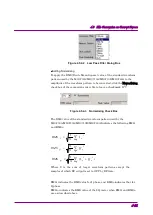
The relationship between the characteristics of the
MG3700A/MG3710A/MG3710E/MG3740A and the RMS value is shown
in Table 4.5.4-2 below:
Table 4.5.4-2 The Relation between the Major Waveform Factors and
RMS Values
Items
RMS value (Larger)
RMS value (Smaller)
Signal distortion
Worse
Better
Floor noise
Better
Worse
Carrier leakage
Better
Worse
Figure 4.5.4-4 RMS Value Dialog Box
When this software is activated in the MG3700 mode;
The output-level performance-guaranteed upper limit value for the RMS
value range and the upper limit setting level for RF output signal
stable-distortion characteristics are shown in the Tables 4.5.4-3 and
4.5.4-4 below.
Table 4.5.4-3 The Maximum Guaranteed Output Level
Frequency
For standard
composition
When a mechanical
attenuator option is
installed.
50 MHz ≤ f ≤ 3 GHz
+2 +
χ
dBm
+7 +
χ
dBm
3 GHz < f
≤
6 GHz (if
Upper limit frequency 6
GHz option is installed)
–1 +
χ
dBm
+4 +
χ
dBm
χ
: RMS value (dB) = 20*log (RMS value/1634) RMS value = 1157 to 1634
Table 4.5.4-4 Normalized Distortion Free Level of RF Output Signal
For standard composition
When a mechanical
attenuator option is
installed.
χ
dBm
+3 +
χ
dBm
χ
: RMS value (dB) = 20*log (RMS value/1634)
RMS value = 1157 to 1634