Chapter 5 Detail Description
5-12
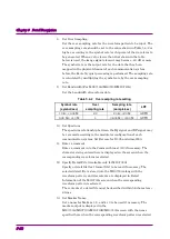
8. Set Over Sampling.
Set the over sampling rate for the waveform pattern to be input. The
over sampling rate should be set to the value shown in Table 5.4-2 or
higher, according to the symbol rate (or chip rate) of the waveform to
be generated. When a value lower than that shown in the table
below is used, the image signal element may become –60 dB or more.
The symbol rate is the output rate for the data that has been
mapped in the physical channel of each communication system
before the Route Nyquist processing is performed. The sampling rate
is calculated by multiplying the symbol rate by the over sampling
rate.
9. Set Bandwidth (For MG3710A/MG3710E/MG3740A)
Set the bandwidth of waveform data.
Table 5.4-2 Over sampling rate setting
Symbol rate
(symbol/sec)
Over
sampling rate
Sampling rate
(sample/sec)
LPF
10 k
≤
,
≤
9.09 M
2.2
20 k
≤
,
≤
20 M
AUTO
9.09 M<,
≤
40 M
4
36.36 M<,
≤
160 M
AUTO
10. Set Spectrum.
The spectrum relationship between the IQ signal and RF signal may
be reversed according to the modulator configuration of each
communication system. Set Reverse for IS-95 and cdma2000.
11. Enter a comment.
Enter a comment into the Comment Lines 1/2/3 if necessary. The
character string entered here is displayed on the screen when the
corresponding waveform is selected.
12. Specify Detail File. (Available only for MG3700A)
Specify a detail file (text-format file) to be read if necessary. The
selected detail file is stored into the MG3700A along with the
waveform pattern, and its contents are displayed in Detail
Information of the MG3700A screen when the corresponding
waveform pattern is selected.
The contents of a detail file must be described within 56 characters
×
6 lines.
13. Set Marker Name.
Set a name for Makers 1, 2, and/or 3 to be used if necessary. The
marker output is displayed in the
MG3700A/MG3710A/MG3710E/MG3740A screen with the name
specified here when the corresponding waveform pattern is selected.

