


Chapter 4 Operations for Each Function
4-178
4.11.9 Auxiliary signal output
When the waveform pattern generated by the W-CDMA Uplink
IQproducer is selected on the mainframe, a marker signal synchronized
with the RF signal is also generated from the mainframe output
connector.
MG3700A
The Frame Trigger signal is generated from the AUX Input/Output
Connector1 on the rear panel.
•
Frame Trigger
The 10 ms interval pulse synchronized to the Frame header symbol is
generated. Change Polarity for Marker 1 to change the signal polarity.
MG3710A/MG3710E
The marker signal is output from Marker 1 and AUX connector on the
rear panel.
The output signal is specified depending on the MG3710A/MG3710E
settings as shown in the Table 4.10.9-1.
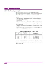
Table 4.11.9-1 MG3710A/MG3710E Marker Signal
Generating
SG
Waveform
memory
Signal name
SG1
Memory A
SG1 Marker1 A
SG1
Memory B
SG1 Marker1 B
SG2
Memory A
SG2 Marker1 A
SG2
Memory B
SG2 Marker1 B
For how to configure marker signal and connector setting, refer to 7.4.2
“Route Output Connectors” in
MG3710A/MG3710E/MG3740A Operation
Manual (Mainframe)
.