


DBS9900 User’s Manual
7-10
DBS9900 Clock
82-28993 Revision 01
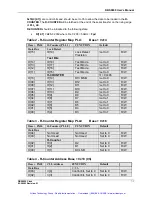
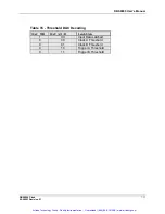
Table 10 - FUNCTION LATCH Address Base + 0x18 (2h or 3h)
Base +
0X18
F Latch (PLL 0)
FUNCTION
Default
Data Bus
C=2h or 3h
D[03]
C[4]
Control bit, set to 0
Set to 0
R/W
D[02]
C[3]
Control bit, set to 0
Set to 0
R/W
D[01]
C[2]
Control bit, set to 1
Set to 0
R/W
D[00]
C[1]
Control bit, set to 0 or 1
Set to 0
R/W
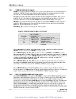
If
C[4:1]
is set to
3h,
the same data as
C[4:1] = 2h
will be loaded into the function latch with the
addition of providing a reset pulse to reset the
R-COUNTER
,
N-COUNTER
and
TIMEOUT
counters. This re-synchronizes the counters.
The power down feature of the LMX2306 is not used on the DBS9900.
F2, F10, F18
should be
set low.
The FastLock function on the LMX2306 is not used on the DBS9900.
F[14:8]
should be set low.
F7
tri-states the charge pump integrator output. For normal operation, set
F7
low.
F6
selects the polarity of the phase detector.
F6
should be set high when the VCO gain slope is
positive.
F6
should be set low when the VCO gain slope is negative. The JTOS-200 VCO has a
positive gain slope. The integrator loop inverts the polarity of the control signal; therefore,
F6
should be set low.
F5
to
F3
control the function of the
FO_LD
(pin14). The internal MUX routes several internal
nodes to pin14. The nodes are listed in the following table.
Bits
F[5:3]
are decoded in the following way:
Table 11 – FO_LD Register Map Base + 0x14
F[5:3]
FO_LD
000
TRI-STATE
001
Digital Lock Detect (Default)
010
N Divider Output (Fpd)
011
Active High
100
R Divider Output (Fpd)
101
N Channel Open Drain Lock Detect
110
Serial Data Output
111
Active Low
Setting
F[5:3]
to
2h
and
4h
is useful to determine if the reference oscillator and VCO are being
properly divided down to
Fpd
. This aids in trouble shooting the PLL.
F[5:3]
set to
1h (Default)
makes digital lock detect available to the host. Under normal operation,
F[5:3]
should be
programmed to
1h
to determine if the PLL is in frequency lock.
F[1]
enables and disables the counter RESET. This function resets the counters internal to the
LMX2306 to their initial reset state. When set high, the counter RESET is enabled. When set low,
the counter RESET is disabled.
Artisan Technology Group - Quality Instrumentation ... Guaranteed | (888) 88-SOURCE | www.artisantg.com


