


DBS9900 User’s Manual
DBS9900 Clock
7-9
82-28993 Revision 01
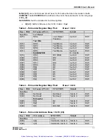
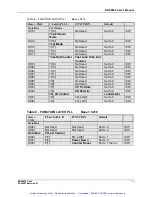
Table 8 - FUNCTION LATCH PLL1
Base + 0x14
Base + 0X14
F Latch (PLL 1)
FUNCTION
Default
Data Bus
Test Mode
D[15]
F[19]
Not Used
Set to 0
R/W
Power Down
Mode
D[14]
F[18]
Not Used
Set to 0
R/W
Test Mode
D[13]
F[17]
Not Used
Set to 0
R/W
D[12]
F[16]
Not Used
Set to 0
R/W
D[11]
F[15]
Not Used
Set to 0
R/W
TimeOut Counter Fast Lock Time Out
Counter
D[10]
F[14]
Not Used
Set to 0
R/W
D[09]
F[13]
Not Used
Set to 0
R/W
D[08]
F[12]
Not Used
Set to 0
R/W
D[07]
F[11]
Not Used
Set to 0
R/W
D[06]
F[10]
Not Used
Set to 0
R/W
D[05]
F[9]
Not Used
Set to 0
R/W
D[04]
F[8]
Not Used
Set to 0
R/W
D[03]
F[7]
CP Tri-State
Set to 0
R/W
D[02]
F[6]
PD Polarity
Set to 0
R/W
FO_LD Control
Lock Detect
D[01]
F[5]
FO_LD[2]
Set to 0
R/W
D[00]
F[4]
FO_LD[1]
Set to 0
R/W
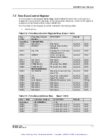
Table 9 - FUNCTION LATCH PLL
Base + 0x16
Base +
0X16
F Latch (PLL 0)
FUNCTION
Default
Data Bus
D[04]
Not Used
Not Used
Set to 0
R/W
D[03]
Not Used
Not Used
Set to 0
R/W
Data Bus
FO_LD Control
D[02]
F[3]
FO_LD[0]
Set to 1
R/W
D[01]
F[2]
Power Down
Set to 0
R/W
D[00]
F[1]
Counter Reset
Set to 1 then 0
R/W
Artisan Technology Group - Quality Instrumentation ... Guaranteed | (888) 88-SOURCE | www.artisantg.com


