DBS9900 User’s Manual
DBS9900 Registers
6-1
82-28993 Revision 01
6 DBS9900 VME / VXI Bus Interface - Registers
The VME / VXI Interface conforms to
Version 1.4
of the VXI specification.
Per VXI definition, the DBS9900 is a
register based servant
device.
Message based protocols
will
not be supported.
Dynamic Configuration
will be supported.
MODID slot detection
and
TTL
backplane triggers
will be supported. The standard
Interface Register Offset Mapping
will be
supported.
Unaligned Transfers
and
Read-Modify-Write Capability
will not be supported. MODID
and TTL Trigger pinouts are per VXI Specification. Operation of the SYSFAIL and INHIBIT are
also per section 3.2.1.1.2 of the VXI Specification.
In terms of the VME specifications, the DBS9900 is an A32: A24: A16: D16: D32: Slave that will
support the following:
•
16-bit word transfers.
•
32-bit word transfers
•
Standard (A24) 16 Mbyte address space (AM codes 39, 3A, 3D, and 3E) jumper
selectable.
•
Extended (A32) 4 Gbyte address space (AM codes 09, 0A, 0D, and 0E) jumper
selectable.
•
Short (A16) 64K address space (AM codes 29 and 2D)
•
Block Transfers (BLT) for memory using AM codes 3B, 3F, 0F, and 0B
•
Maskable interrupt generation on one of 7 register programmable levels
•
The DBS9900
does not
support Bus Request or Bus Arbitration.
•
The DBS9900
is never
a Bus Master Device.
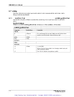
The DBS9900 allows for two independent daughter board modules, accessed via module
interface connectors (on the DBS9900). The DBS9900 is ONE DEVICE as defined by VXI
conventions, but is actually two independent devices functionally.
The DBS9900 supports D32 transfers to the daughter board module registers/memory only (0x20
– 0x3E). D32 transfers are not supported to the registers physically located on the DBS9900
mother board (0x00 – 0x1E). D16 transfers must be used to access these mother board
registers.
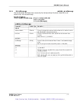
The DBS9900 can generate interrupts, but CANNOT request data bus operations as a bus
master. Interrupts may be generated on one of seven levels. Interrupt sources are maskable and
readable. The Interrupt Level is register programmable, and the interrupt will be cleared during
the interrupt service STATUS ID cycle, in accordance with the VME-defined
ROAK
protocol.
Because the DBS9900 can accommodate two daughter board modules, the interrupt service
routine checks and clears
both
interrupt registers on the rider modules when servicing an
interrupt.
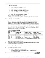
The DBS9900 registers are accessed in A16 mode at a base address set by Dynamic
Configuration.
The A16 addresses from 0x00 to 0x1E reside on the DBS9900. The A16 addresses from 0x20 to
0x3E reside on each module and the functions are defined in the individual module specs. Each
module can be accessed by switching in its DEVICE dependent Registers into this space. This is
done by setting a bit in the Module / Relay Select Register. This register also controls relays to
program the CAL front panel connectors.
The data and address busses will be static if the VXI bus is not accessing registers on the
module. The interface clock will operate in a burst mode, only during VXI bus cycles involving the
Artisan Technology Group - Quality Instrumentation ... Guaranteed | (888) 88-SOURCE | www.artisantg.com


