Measurement Techniques and Sources of Error
Voltage Measurements
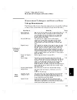
The following table shows voltage measurement error sources. Each of these
sources of error is described in more detail in the sections that follow.
Error Source
Correction
Page
Cabling and
connection
related
Radio Frequency
Interference (RFI)
Special circuits and shields are used to minimize the effects of
RFI in the measurement. Low emission of RFI also allows the
use of the meter with sensitive devices such as Josephson
junctions where high frequency signals may interfere with
proper operation of the device.
Thermal EMF Errors
The meter has 99% copper terminals with soldered
connections. The test leads are copper wire with crimped
copper terminals. These test connectors and leads are
recommended to help minimize the effects of thermal EMF
errors.
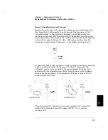
Magnetic Loops
Use twisted-pair connections to the meter to reduce the noise
pickup loop area, or dress the test leads as close together as
possible. Loose or vibrating test leads will also induce error
voltages. Make sure your test leads are tied down securely
when operating near magnetic fields. Whenever possible, use
magnetic shielding materials or physical separation to reduce
problem magnetic field sources. Use NPLC
≥
1 if the pickup is
power line related.
Power Line Rejection
(NMR)
Set the integration time to 1 or more PLCs.
Ground Loops
The best way to eliminate ground loops is to maintain the
meter’s isolation from earth; do not connect the input terminals
to ground. If the meter must be earth-referenced, be sure to
connect it, and the device-under-test, to the same common
ground point. This will reduce or eliminate any voltage
difference between the devices. Also make sure the meter and
device-under-test are connected to the same electrical outlet
whenever possible.
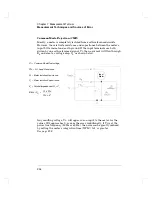
Common Mode Rejection
Reduce the series resistance or common mode voltage.
Meter
related
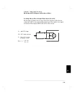
Loading Errors
The meter’s input resistance is > 10 G
Ω
for 1 mV to 10 V
ranges,
10 M
Ω
for 100 volt range.
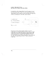
Input Bias Current
(Leakage Current)
The meter’s measuring circuitry exhibits approximately 30pA
of input bias current for ambient temperatures from 0°C to
30°C. Bias current will change at temperatures different than
those at which the meter was calibrated.
Injected Current
A circuit may or may not be sensitive to injected current
depending on the topology of circuit being measured by the
voltmeter, the impedance level of the circuit, and the common
mode or normal mode rejection of the meter.
7
Chapter 7 Measurement Tutorial
Measurement Techniques and Sources of Error
249
Содержание 34420A
Страница 1: ......
Страница 2: ......
Страница 13: ...1 Quick Start ...
Страница 31: ...2 Front Panel Operation ...
Страница 55: ...3 Features and Functions ...
Страница 117: ...4 Remote Interface Reference ...
Страница 200: ...5 Error Messages ...
Страница 213: ...6 Application Programs ...
Страница 245: ...6 Chapter 6 Application Programs Microsoft Excel Macro Example 245 ...
Страница 246: ...Chapter 6 Application Programs Microsoft Excel Macro Example 246 ...
Страница 247: ...7 Measurement Tutorial ...
Страница 274: ...8 Specifications ...
Страница 279: ...Dimensions Chapter 8 Specifications 34420A Nano Volt Micro Ohm Meter 280 ...
Страница 294: ......

