


To test the offset accuracy (oscilloscope)
Testing the offset accuracy verifies the performance of the following specification:
•
Offset accuracy
Equipment Required
Equipment
Critical Specifications
Recommended
Model/Part
DC Power Supply
−
35.000 to +35.000 Vdc,
±
1 mV resolution
3245A option 002
Digital Multimeter
Better than 0.1% accuracy
3458A
Cable
BNC (m)(m) 48-inch
8120-1840
Adapter (cable to
power supply)
BNC (f) to Dual Banana Plug
1251-2277
Adapter
BNC tee (m)(f)(f)
1250-0781
Blocking Capacitor
BNC (m)(f) 0.18
µ
F,
±
200 V
10240B
BNC Shorting Cap
1250-0074
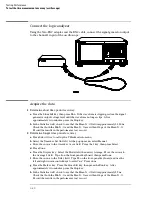
Set up the equipment
Turn on the equipment required and the logic analyzer. Let them warm up for 30
minutes if you have not already done so.
3–67
Содержание 1670G Series
Страница 20: ...1 12...
Страница 116: ...Testing Performance Performance Test Record pattern generator 3 92...
Страница 126: ...Calibrating and Adjusting To test the CAL OUTPUT ports 4 10...
Страница 166: ...Exploded View of the Agilent 1670G series logic analyzer Replacing Assemblies 6 4...
Страница 186: ...Exploded View Exploded view of the Agilent 1670G series logic analyzer Replaceable Parts Exploded View 7 4...
Страница 197: ...The Logic Acquisition Board Logic Acquisition Board Block Diagram Theory of Operation The Logic Acquisition Board 8 7...
Страница 200: ...The Oscilloscope Board Oscilloscope Board Block Diagram Theory of Operation The Oscilloscope Board 8 10...
Страница 201: ...Theory of Operation The Oscilloscope Board 8 11...


