


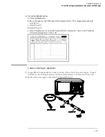


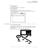


Connect the logic analyzer
Using the BNC-to-banana adapters, connect one end of each BNC cable to the 4-wire
resistance connections on the multimeter, and connect the free ends of the cables to the BNC
Tee. Connect the male end of the BNC tee to the channel 1 input of the oscilloscope module.
Testing Performance
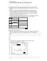
To test the input resistance (oscilloscope)
3–61
Содержание 1670G Series
Страница 20: ...1 12...
Страница 116: ...Testing Performance Performance Test Record pattern generator 3 92...
Страница 126: ...Calibrating and Adjusting To test the CAL OUTPUT ports 4 10...
Страница 166: ...Exploded View of the Agilent 1670G series logic analyzer Replacing Assemblies 6 4...
Страница 186: ...Exploded View Exploded view of the Agilent 1670G series logic analyzer Replaceable Parts Exploded View 7 4...
Страница 197: ...The Logic Acquisition Board Logic Acquisition Board Block Diagram Theory of Operation The Logic Acquisition Board 8 7...
Страница 200: ...The Oscilloscope Board Oscilloscope Board Block Diagram Theory of Operation The Oscilloscope Board 8 10...
Страница 201: ...Theory of Operation The Oscilloscope Board 8 11...


