


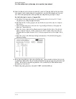


8
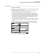
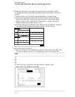
Using the Delay mode of the pulse generator channel 1, position the pulses
according to the setup/hold combination selected, +0.0 ps or -100 ps.
a
On the Oscilloscope, select [Define meas] Define
∆
Time - Stop edge: falling.
b
On the oscilloscope, select [Shift]
∆
Time. Select Start src: channel 1, then select
[Enter] to display the setup time (
∆
Time(1)-(2)).
c
Adjust the pulse generator channel 1 Delay until the pulses are aligned according the
the setup time of the setup/hold combination selected, +0.0 ps or -100 ps.
Disregard the oscilloscope Period(2) value. The settings provided in this procedure
measure the period from rising edge to rising edge, which is not a valid measurement.
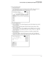
9
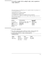
Select the clocks to be tested.
a
Select the clock field to be tested, then select the clock edges as indicated in the table.
Clocks
J
↓
+ K
↓
+ L
↓
+ M
↓
b
Select Done to exit the Master Clock menu.
Testing Performance
To test the multiple-clock, multiple-edge, state acquisition (logic analyzer)
3–39
Содержание 1670G Series
Страница 20: ...1 12...
Страница 116: ...Testing Performance Performance Test Record pattern generator 3 92...
Страница 126: ...Calibrating and Adjusting To test the CAL OUTPUT ports 4 10...
Страница 166: ...Exploded View of the Agilent 1670G series logic analyzer Replacing Assemblies 6 4...
Страница 186: ...Exploded View Exploded view of the Agilent 1670G series logic analyzer Replaceable Parts Exploded View 7 4...
Страница 197: ...The Logic Acquisition Board Logic Acquisition Board Block Diagram Theory of Operation The Logic Acquisition Board 8 7...
Страница 200: ...The Oscilloscope Board Oscilloscope Board Block Diagram Theory of Operation The Oscilloscope Board 8 10...
Страница 201: ...Theory of Operation The Oscilloscope Board 8 11...


