


4
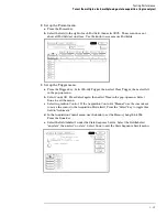
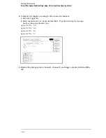
Configure the trigger according to the connected channels.
a.
Press the Trigger key.
b.
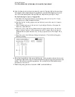
Select the field next to the pattern recognizer "a" under the label Bus1. Type the
following for your logic analyzer, then press Select.
Agilent 1670G – "AA"
Agilent 1672G – "AA"
Agilent 1671G – "2A"
Agilent 1673G – "A"
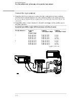
5
Enable the pulse generator channel 1, channel 2, and trigger ouputs (with the LEDs
off).
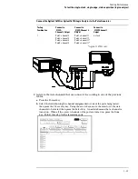
Testing Performance
To test the multiple-clock, multiple-edge, state acquisition (logic analyzer)
3–34
Содержание 1670G Series
Страница 20: ...1 12...
Страница 116: ...Testing Performance Performance Test Record pattern generator 3 92...
Страница 126: ...Calibrating and Adjusting To test the CAL OUTPUT ports 4 10...
Страница 166: ...Exploded View of the Agilent 1670G series logic analyzer Replacing Assemblies 6 4...
Страница 186: ...Exploded View Exploded view of the Agilent 1670G series logic analyzer Replaceable Parts Exploded View 7 4...
Страница 197: ...The Logic Acquisition Board Logic Acquisition Board Block Diagram Theory of Operation The Logic Acquisition Board 8 7...
Страница 200: ...The Oscilloscope Board Oscilloscope Board Block Diagram Theory of Operation The Oscilloscope Board 8 10...
Страница 201: ...Theory of Operation The Oscilloscope Board 8 11...


