


Perform Test All
Selecting Perform Test All will initiate all of the previous functional verification tests in the
order they are listed. The failure of any or all of the tests will be reported in the test menu
field of each of the tests. The Perform All Test will not initiate the Front Panel Test or the
Display Test.
Front Panel Test
A mock-up of the logic analyzer front panel is displayed on the CRT when the Front Panel
Test is initiated. The operator then pushes each front panel button and turns the RPG (rotary
pulse generator) knob to toggle the corresponding fields from light to dark on the front panel
mock-up. Successively pushing any front panel key will cause the corresponding field to
toggle back and forth between light and dark. An exception is the Done key. Pressing the
Done key a second time will cause an exit of this test.
The Front Panel Test passes when all of the key fields in the front panel mock-up on the CRT
can be toggled by pressing the corresponding front panel key, and the two RPG fields can be
toggled by turning the knob. The Front Panel Test is not called when Perform Test All is
selected.
Display Test
When initiated, the display test will cause three test screens to be displayed sequentially. The
first test screen is a test pattern used to align the CRT. The other two screens verify correct
operation of the greyscale palette by displaying first a full-bright screen and then a half-bright
screen.
The pass or fail status of the display test is determined by the operator. The Display Test
passes when all three test screens are displayed according to chapter 4, "Calibrating and
Adjusting." The display test is not used when Perform Test All is selected.
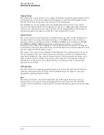
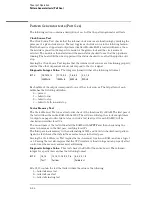
LAN Test
The LAN test verifies the functionality of the LAN circuitry on the logic analyzer CPU board. A
status code is returned for each of the LAN tests when each test is completed. The following
figure shows the bit positions of the hexidecimal status reporting word.
A "1" in a bit position signifies that the bit is set and the test failed.
A "0" in a bit position signifies that the bit is not set and the test passed.
Status Reporting Message
Theory of Operation
System Tests (SysPV)
8–21
Содержание 1670G Series
Страница 20: ...1 12...
Страница 116: ...Testing Performance Performance Test Record pattern generator 3 92...
Страница 126: ...Calibrating and Adjusting To test the CAL OUTPUT ports 4 10...
Страница 166: ...Exploded View of the Agilent 1670G series logic analyzer Replacing Assemblies 6 4...
Страница 186: ...Exploded View Exploded view of the Agilent 1670G series logic analyzer Replaceable Parts Exploded View 7 4...
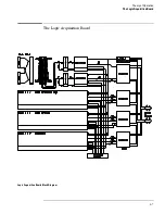
Страница 197: ...The Logic Acquisition Board Logic Acquisition Board Block Diagram Theory of Operation The Logic Acquisition Board 8 7...
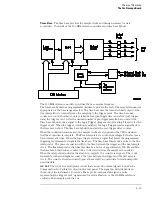
Страница 200: ...The Oscilloscope Board Oscilloscope Board Block Diagram Theory of Operation The Oscilloscope Board 8 10...
Страница 201: ...Theory of Operation The Oscilloscope Board 8 11...


