
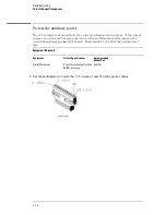


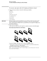


To remove and replace the power supply
1
Using previous procedures, remove the following assemblies:
•
Handle
•
Rear Feet
•
Cover
•
Disk Drive Assembly
•
Acquisition Board
•
CPU Board
•
Rear Panel
W A R N I N G
Hazardous voltages exist on the power supply. To avoid electrical shock, disconnect the
power from the instrument before performing the following procedures. After disconnecting
the power, wait at least three minutes for the capacitors to discharge before continuing.
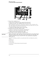
2
Disconnect the power switch cable from the power supply power on/off connector.
3
Using a Torx T-15 screwdriver, remove two screws on the bottom toward the front
of the instrument that secure the power supply to the bottom of the chassis..
4
Loosen the remaining two T-15 screws on the bottom toward the rear of the
instrument.
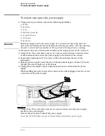
5
Slide the power supply toward the rear of the instrument approx. 12 mm (1/2) inch),
then lift the power supply out of the chassis
6
Unplug the power supply output cables and power sense cables from the power
supply.
When installing the power sense cable, ensure each cable is plugged onto the correct
connectors of the power supply.
7
Using a Torx T-15 screwdriver, remove two screws that secure the power supply
bracket to the power supply.
Reverse this procedure to install the power supply.
Check that the LCD Display is properly installed before installing the power supply.
Replacing Assemblies
To remove and replace the power supply
6–12
Содержание 1670G Series
Страница 20: ...1 12...
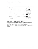
Страница 116: ...Testing Performance Performance Test Record pattern generator 3 92...
Страница 126: ...Calibrating and Adjusting To test the CAL OUTPUT ports 4 10...
Страница 166: ...Exploded View of the Agilent 1670G series logic analyzer Replacing Assemblies 6 4...
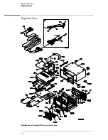
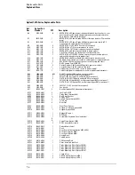
Страница 186: ...Exploded View Exploded view of the Agilent 1670G series logic analyzer Replaceable Parts Exploded View 7 4...
Страница 197: ...The Logic Acquisition Board Logic Acquisition Board Block Diagram Theory of Operation The Logic Acquisition Board 8 7...
Страница 200: ...The Oscilloscope Board Oscilloscope Board Block Diagram Theory of Operation The Oscilloscope Board 8 10...
Страница 201: ...Theory of Operation The Oscilloscope Board 8 11...


