


Verify the DC CAL OUTPUT port
1
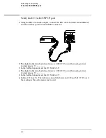
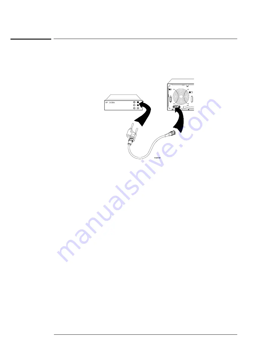
Using the BNC-to-banana adapter, connect the BNC cable between the multimeter
and the oscilloscope DC CAL OUTPUT connector.
2
The digital voltmeter should read close to 0.0000 V. Record the reading to four
decimal places. V
1
= _______.
3
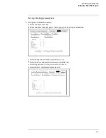
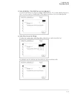
In the Calibration menu set the DC Volts to 5 V.
4
The digital voltmeter should read close to 5.0000 V. Record the reading to four
decimal places. V
2
= _______.
5
In the Calibration menu set the DC Volts to 0 V.
6
Subtract V
1
from V
2
. The difference should be between 4.990 and 5.010 V. Record
the reading in the performance test record.
Calibrating and Adjusting
To test the CAL OUTPUT ports
4–8
Содержание 1670G Series
Страница 20: ...1 12...
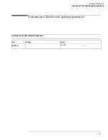
Страница 116: ...Testing Performance Performance Test Record pattern generator 3 92...
Страница 126: ...Calibrating and Adjusting To test the CAL OUTPUT ports 4 10...
Страница 166: ...Exploded View of the Agilent 1670G series logic analyzer Replacing Assemblies 6 4...
Страница 186: ...Exploded View Exploded view of the Agilent 1670G series logic analyzer Replaceable Parts Exploded View 7 4...
Страница 197: ...The Logic Acquisition Board Logic Acquisition Board Block Diagram Theory of Operation The Logic Acquisition Board 8 7...
Страница 200: ...The Oscilloscope Board Oscilloscope Board Block Diagram Theory of Operation The Oscilloscope Board 8 10...
Страница 201: ...Theory of Operation The Oscilloscope Board 8 11...


