


Verify the test signal
1
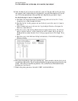
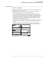
Check the clock period. Using the oscilloscope, verify that the master-to-master
clock time is 6.666 ns, +0 ps or
−
100 ps.
a
In the oscilloscope Timebase menu, select Scale: 1.000 ns/div.
b
In the oscilloscope Timebase menu, select Position. Using the oscilloscope knob,
position the clock waveform so that a rising edge appears at the left of the display.
c
On the oscilloscope, select [Shift] Period: channel 2, then select [Enter] to display the
clock period (Period(2)). If the period is not less than 6.666 ns, go to step d. If the
period is less than 6.666 ns, go to step 2.
d
In the oscilloscope Timebase menu, increase Position 6.666 ns. If the period is not less
than 6.666 ns, decrease the pulse generator Period in 10 ps increments until one of the
two periods measured is less than 6.666 ns.
2
Check the data pulse width. Using the oscilloscope verify that the data pulse width
is 4.000 ns, +0 ps or
−
100 ps.
a
In the oscilloscope Timebase menu, select Position. Using the oscilloscope knob,
position the data waveform so that the waveform is centered on the screen.
b
On the oscilloscope, select [Shift] + width: channel 1, then select [Enter] to display the
data signal pulse width (+ width (1)).
c
If the pulse width is outside the limits, adjust the pulse generator channel 2 width until
the pulse width is within limits.
Testing Performance
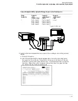
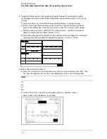
To test the multiple-clock, multiple-edge, state acquisition (logic analyzer)
3–35
Содержание 1670G Series
Страница 20: ...1 12...
Страница 116: ...Testing Performance Performance Test Record pattern generator 3 92...
Страница 126: ...Calibrating and Adjusting To test the CAL OUTPUT ports 4 10...
Страница 166: ...Exploded View of the Agilent 1670G series logic analyzer Replacing Assemblies 6 4...
Страница 186: ...Exploded View Exploded view of the Agilent 1670G series logic analyzer Replaceable Parts Exploded View 7 4...
Страница 197: ...The Logic Acquisition Board Logic Acquisition Board Block Diagram Theory of Operation The Logic Acquisition Board 8 7...
Страница 200: ...The Oscilloscope Board Oscilloscope Board Block Diagram Theory of Operation The Oscilloscope Board 8 10...
Страница 201: ...Theory of Operation The Oscilloscope Board 8 11...


