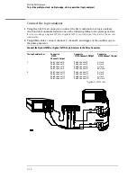


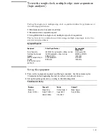


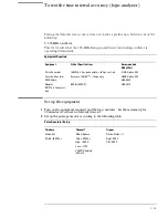


Connect the Agilent 1672G or 1673G Logic Analyzer to the Pulse Generator
Testing
Combination
Connect to
8133A
Channel 2 Output
Connect to
8133A Channel 2
Output
Connect to
8133A Channel 1
Output
1
Pod 1, channel 3
Pod 2, channel 3
Pod 3, channel 3
Pod 4, channel 3
Pod 1, channel 3
Pod 2, channel 3
Pod 3, channel 3 *
Pod 4, channel 3 *
J-clock
*Agilent 1672G only
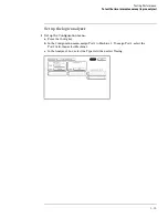
3
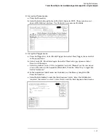
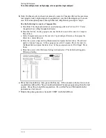
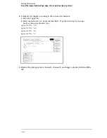
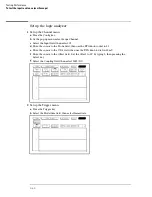
Activate the data channels that are connected according to one of the previous
tables.
a
Press the Format key.
b
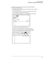
Select the field showing the channel assignments for one of the pods being tested.
Press the Clear entry key. Using the arrow keys, move the selector to the data
channels to be tested, then press the Select key. An asterisk means that a channel is
turned on. When all the correct channels of the pod are turned on, press the Done
key. Follow this step for the remaining pods.
Testing Performance
To test the single-clock, multiple-edge, state acquisition (logic analyzer)
3–45
Содержание 1670G Series
Страница 20: ...1 12...
Страница 116: ...Testing Performance Performance Test Record pattern generator 3 92...
Страница 126: ...Calibrating and Adjusting To test the CAL OUTPUT ports 4 10...
Страница 166: ...Exploded View of the Agilent 1670G series logic analyzer Replacing Assemblies 6 4...
Страница 186: ...Exploded View Exploded view of the Agilent 1670G series logic analyzer Replaceable Parts Exploded View 7 4...
Страница 197: ...The Logic Acquisition Board Logic Acquisition Board Block Diagram Theory of Operation The Logic Acquisition Board 8 7...
Страница 200: ...The Oscilloscope Board Oscilloscope Board Block Diagram Theory of Operation The Oscilloscope Board 8 10...
Страница 201: ...Theory of Operation The Oscilloscope Board 8 11...


