


Pattern Generator tests (Patt Gen)
The following section contains a description of each of the the pattern generator self tests.
Clock Source Test
The Clock Source Test checks that the internal clock sources are functioning by verifying the
presence of a given clock source. The test toggles each clock source in the following fashion.
First the board is stopped and outputs are disabled. Module RAM is loaded with zeros, then
the module is placed in the respective mode for the given clock and the clock source is
selected. The module is then started and the main status checked to see that the pipeline is
running. The board will then be stopped and the status checked to see that the pipeline did
stop.
Passing the Clock Source Test implies that the internal clock sources are functioning properly,
and that the other dependent subcircuits respond to the clock signal.
Diagnostic Integer Value:
The integer returned will have the following bit format:
BIT #:
15, 14,13, 12
11, 10, 9, 8
7, 6, 5, 4
3, 2, 1, 0
200M clk
100M clk
50M clk
PLD clk
Each nibble of the output corresponds to one of the clock sources. The bit pattern of each
nibble has the following definition:
0 — passed
1 — failed to run
2 — failed to stop
3 — failed to both run and stop
Vector Memory Test
The Vector Memory Test does a first order check of the functionality of RAM. The first pass of
the test will load the entire RAM with 0x0000. The software will step the clock enough times
to output one page worth of data. At each clock a test read port for each RAM IC will be
checked and verified for all 0s.
The second pass of the test will load all the RAMS with 0xFFFF and then check using the
same technique as in the first pass, verifying for all Fs.
The third pass loads memory with an alternating 0x5555 and 0xAAAA checkerboard pattern.
Again the test checks the data in the same fashion as in the first pass.
Passing the Vector Memory Test implies that each memory location in RAM can store a logic 1
or 0. Passing the test also implies that the CPU interface is functioning and can properly affect
control over the memory and memory addressing.
Diagnostic Integer Value:
This test checks the RAM of the entire board. The returned
integer for a particular card has the following format:
BIT #:
15, 14
13, 12, 11, 10, 9, 8, 7, 6
5, 4, 3, 2, 1, 0
Test 1
Fail row
Failed test
Bits 14,15 contain the test that failed where the value is the following:
1— failed all zeros test
2— failed all ones test
3— failed alternating test
Theory of Operation
Pattern Generator tests (Patt Gen)
8–26
Содержание 1670G Series
Страница 20: ...1 12...
Страница 116: ...Testing Performance Performance Test Record pattern generator 3 92...
Страница 126: ...Calibrating and Adjusting To test the CAL OUTPUT ports 4 10...
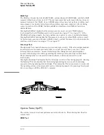
Страница 166: ...Exploded View of the Agilent 1670G series logic analyzer Replacing Assemblies 6 4...
Страница 186: ...Exploded View Exploded view of the Agilent 1670G series logic analyzer Replaceable Parts Exploded View 7 4...
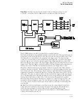
Страница 197: ...The Logic Acquisition Board Logic Acquisition Board Block Diagram Theory of Operation The Logic Acquisition Board 8 7...
Страница 200: ...The Oscilloscope Board Oscilloscope Board Block Diagram Theory of Operation The Oscilloscope Board 8 10...
Страница 201: ...Theory of Operation The Oscilloscope Board 8 11...


